Part Datasheet Review and Updates
2:18
Evaluating file usage.
Searching the project.
Analyzing the PCB layout.
Analyzing the schematic.
Searching for project components.
Searching 3 domains.
Looking for "Exact manufacturer part number, manufacturer name, package style, mounting style, switch configuration, number of positions, number of terminals/pins, dimensions, ratings, and product description from the datasheet." in SLW-864574-5A-RA-N-D.pdf
Looking for "Complete terminal or pin table, including terminal numbering/names and function for the SLW-864574-5A-RA-N-D slide switch." in SLW-864574-5A-RA-N-D.pdf
Looking for "Mechanical package and recommended PCB footprint details, including hole pattern, pin spacing, overall dimensions, and any land pattern information for SLW-864574-5A-RA-N-D." in SLW-864574-5A-RA-N-D.pdf
Looking for "Explain the electrical function of each terminal and the switching truth table or connection states for the 5-position slide switch SLW-864574-5A-RA-N-D." in SLW-864574-5A-RA-N-D.pdf
Refining component search.
Searching 2 domains.
Searching fetch_url.
Looking for "pin descriptions, terminal numbering 1 2 3 4 5, mounting holes MH1 MH2, package type, footprint or dimensions for SLW-864574-5A-RA-N-D" in SLW-864574-5A-RA-N-D.pdf
Identifying project properties.
Search complete — 105 results across 5 domains.
Reviewing document citations.
Summarizing key specifications.
Datasheet URL, so I did not search for or update it. The current project metadata already includes:Manufacturer Part Number: SLW-864574-5A-RA-N-DManufacturer Name: Same SkyMount: Through HoleDesignator Prefix: SDatasheet URL: official Same Sky PDF
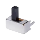
- Slide switch
- SPDT
- Non-shorting
- Right-angle
- Through-hole
- 2 positions
- 3 electrical terminals
- 2 mechanical mounting tabs / anchor posts
- Rated 50 Vdc
- Rated 500 mA
- Contact resistance 100 mΩ max
- Insulation resistance 100 MΩ min @ 500 Vdc
- Withstanding voltage 500 Vac for 1 minute
- Operating temperature -20 °C to 70 °C
- Storage temperature -25 °C to 70 °C
- Mechanical life 10,000 cycles
- Body size reported as 8.6 x 4.5 x 6.2 mm in the product description, while one extracted source line also surfaced 7.4 mm overall height, so the height dimension should be treated carefully and verified directly from the drawing before finalizing library metadata.
Pin Number values are:- Pin/terminal count looks plausible and likely correct for this switch footprint:
- 3 electrical pins
- 2 mechanical support pins
- The PCB layout also contains five pads with matching names:
- the project has the right count
- the footprint has the right class of pads
- but I cannot fully prove the exact terminal numbering-to-function mapping from the extracted datasheet text alone
Pin Type = Unspecified:- 1, 2, 3: likely Passive
- MH1, MH2: likely Passive or mechanical-only handling depending on how you want this part modeled
- common/wiper terminal
- throw A
- throw B
- mounting tab 1
- mounting tab 2
Part Type is Electromechanical Components. That is not necessarily wrong, but it is fairly broad. A more specific value like Switch or Slide Switch would be better if Flux supports that category.A stronger version would be something like:
SPDT non-shorting slide switch, right-angle through-hole, 2 position, 50 Vdc 500 mA
- 8.6 x 4.5 x 6.2 mm
- and 8.6 x 4.5 x 7.4 mm
- footprint topology appears correct
- exact land pattern dimensions remain unverified
- Official datasheet URL already present
- MPN and manufacturer match
- Mounting style matches
- Symbol and footprint both appear to represent a 3-terminal SPDT slide switch with 2 mounting tabs
- Total pad count is likely correct
- All terminal
Pin Typefields are still Unspecified - Pin descriptions are missing
- Terminal functional mapping is not yet confirmed from the extracted datasheet text
- Part Type could be made more specific
- Description could be tightened up
- Mechanical dimensions should be verified against the drawing because of the 6.2 mm vs 7.4 mm extraction inconsistency


Welcome 👋
Flux accelerates your PCB design with AI.
Create your account to start using this component and bring your ideas to life.