Connector Part Review and Datasheet Update
3 days
Review all available part information (MPN, package, pin count, description, properties). If no datasheet URL is already set, search the web for the official datasheet and update the part's Datasheet property with the URL. Then cross-check the schematic symbol, footprint, and pin descriptions against the datasheet. Summarize key specs and flag any mismatches.
Thought for 4 sec
3 days
I’ll review the connector metadata, confirm the datasheet URL, then compare the symbol, footprint, and pin descriptions against the official Hirose documentation and report any mismatches.
Worked for 3 mins 1 sec
3 days
Completed the part review and cross-check. The connector identity, 100-pin schematic symbol, and 100-pad 0.4 mm SMT footprint are broadly consistent with Hirose’s official DF40C-100DS-0.4V(51) information; the Datasheet URL was already set, so I did not overwrite it.
Open items flagged:
- Package metadata is incomplete/weak.
- BOM is empty for this part project.
- Datasheet property points to an uploaded PDF rather than the official Hirose URL.
- Pin descriptions are generic numbered terminals, which is expected for this connector.
- Layout tree shows a unit/display anomaly, but the embedded KiCad footprint dimensions look correct.
Full review saved in the project file:
part-review-df40c-100ds-0p4v51.Fix metadata and checks
Add official URL
Improve package metadata
Rerun part review
Verify footprint geometry
Reviews
 A generic fixed inductor suitable for rapid circuit topology development. The footprint automatically adapts based on the selected package, supporting standard SMD sizes (e.g., 0402, 0603, 0805) as well as well-known inductor packages such as SDR1806, PA4320, SRN6028, and SRR1260. Standard inductor values: 1.0 nH, 10 nH, 100 nH, 1.0 µH, 10 µH, 100 µH, 1.0 mH 1.2 nH, 12 nH, 120 nH, 1.2 µH, 12 µH, 120 µH, 1.2 mH 1.5 nH, 15 nH, 150 nH, 1.5 µH, 15 µH, 150 µH, 1.5 mH 1.8 nH, 18 nH, 180 nH, 1.8 µH, 18 µH, 180 µH, 1.8 mH 2.2 nH, 22 nH, 220 nH, 2.2 µH, 22 µH, 220 µH, 2.2 mH 2.7 nH, 27 nH, 270 nH, 2.7 µH, 27 µH, 270 µH, 2.7 mH 3.3 nH, 33 nH, 330 nH, 3.3 µH, 33 µH, 330 µH, 3.3 mH 3.9 nH, 39 nH, 390 nH, 3.9 µH, 39 µH, 390 µH, 3.9 mH 4.7 nH, 47 nH, 470 nH, 4.7 µH, 47 µH, 470 µH, 4.7 mH 5.6 nH, 56 nH, 560 nH, 5.6 µH, 56 µH, 560 µH, 5.6 mH 6.8 nH, 68 nH, 680 nH, 6.8 µH, 68 µH, 680 µH, 6.8 mH 8.2 nH, 82 nH, 820 nH, 8.2 µH, 82 µH, 820 µH, 8.2 mH #generics #CommonPartsLibraryjharwinbarrozo16.2k
- A generic fixed capacitor ideal for rapid circuit topology development. You can choose between polarized and non-polarized types, its symbol and the footprint will automatically adapt based on your selection. Supported options include standard SMD sizes for ceramic capacitors (e.g., 0402, 0603, 0805), SMD sizes for aluminum electrolytic capacitors, and through-hole footprints for polarized capacitors. Save precious design time by seamlessly add more information to this part (value, footprint, etc.) as it becomes available. Standard capacitor values: 1.0pF, 10pF, 100pF, 1000pF, 0.01uF, 0.1uF, 1.0uF, 10uF, 100uF, 1000uF, 10000uF 1.1pF, 11pF, 110pF, 1100pF 1.2pF, 12pF, 120pF, 1200pF 1.3pF, 13pF, 130pF, 1300pF 1.5pF, 15pF, 150pF, 1500pF, 0.015uF, 0.15uF, 1.5uF, 15uF, 150uF, 1500uF 1.6pF, 16pF, 160pF, 1600pF 1.8pF, 18pF, 180pF, 1800pF 2.0pF, 20pF, 200pF, 2000pF 2.2pF, 22pF, 220pF, 2200pF, 0.022uF, 0.22uF, 2.2uF, 22uF, 220uF, 2200uF 2.4pF, 24pF, 240pF, 2400pF 2.7pF, 27pF, 270pF, 2700pF 3.0pF, 30pF, 300pF, 3000pF 3.3pF, 33pF, 330pF, 3300pF, 0.033uF, 0.33uF, 3.3uF, 33uF, 330uF, 3300uF 3.6pF, 36pF, 360pF, 3600pF 3.9pF, 39pF, 390pF, 3900pF 4.3pF, 43pF, 430pF, 4300pF 4.7pF, 47pF, 470pF, 4700pF, 0.047uF, 0.47uF, 4.7uF, 47uF, 470uF, 4700uF 5.1pF, 51pF, 510pF, 5100pF 5.6pF, 56pF, 560pF, 5600pF 6.2pF, 62pF, 620pF, 6200pF 6.8pF, 68pF, 680pF, 6800pF, 0.068uF, 0.68uF, 6.8uF, 68uF, 680uF, 6800uF 7.5pF, 75pF, 750pF, 7500pF 8.2pF, 82pF, 820pF, 8200pF 9.1pF, 91pF, 910pF, 9100pF #generics #CommonPartsLibraryjharwinbarrozo1.5M
- A generic fixed resistor ideal for rapid circuit topology development. Its footprint automatically adapts based on the selected package case code—supporting 0402, 0603, 0805, 1203, and many other standard SMD packages, as well as axial horizontal and vertical configurations. Save precious design time by seamlessly add more information to this part (value, footprint, etc.) as it becomes available. Standard resistor values: 1.0 ohm, 10 ohm, 100 ohm, 1.0k ohm, 10k ohm, 100k ohm, 1.0M ohm 1.1 ohm, 11 ohm, 110 ohm, 1.1k ohm, 11k ohm, 110k ohm, 1.1M ohm 1.2 ohm, 12 ohm, 120 ohm, 1.2k ohm, 12k ohm, 120k ohm, 1.2M ohm 1.3 ohm, 13 ohm, 130 ohm, 1.3k ohm, 13k ohm, 130k ohm, 1.3M ohm 1.5 ohm, 15 ohm, 150 ohm, 1.5k ohm, 15k ohm, 150k ohm, 1.5M ohm 1.6 ohm, 16 ohm, 160 ohm, 1.6k ohm, 16k ohm, 160k ohm, 1.6M ohm 1.8 ohm, 18 ohm, 180 ohm, 1.8K ohm, 18k ohm, 180k ohm, 1.8M ohm 2.0 ohm, 20 ohm, 200 ohm, 2.0k ohm, 20k ohm, 200k ohm, 2.0M ohm 2.2 ohm, 22 ohm, 220 ohm, 2.2k ohm, 22k ohm, 220k ohm, 2.2M ohm 2.4 ohm, 24 ohm, 240 ohm, 2.4k ohm, 24k ohm, 240k ohm, 2.4M ohm 2.7 ohm, 27 ohm, 270 ohm, 2.7k ohm, 27k ohm, 270k ohm, 2.7M ohm 3.0 ohm, 30 ohm, 300 ohm, 3.0K ohm, 30K ohm, 300K ohm, 3.0M ohm 3.3 ohm, 33 ohm, 330 ohm, 3.3k ohm, 33k ohm, 330k ohm, 3.3M ohm 3.6 ohm, 36 ohm, 360 ohm, 3.6k ohm, 36k ohm, 360k ohm, 3.6M ohm 3.9 ohm, 39 ohm, 390 ohm, 3.9k ohm, 39k ohm, 390k ohm, 3.9M ohm 4.3 ohm, 43 ohm, 430 ohm, 4.3k ohm, 43K ohm, 430K ohm, 4.3M ohm 4.7 ohm, 47 ohm, 470 ohm, 4.7k ohm, 47k ohm, 470k ohm, 4.7M ohm 5.1 ohm, 51 ohm, 510 ohm, 5.1k ohm, 51k ohm, 510k ohm, 5.1M ohm 5.6 ohm, 56 ohm, 560 ohm, 5.6k ohm, 56k ohm, 560k ohm, 5.6M ohm 6.2 ohm, 62 ohm, 620 ohm, 6.2k ohm, 62K ohm, 620K ohm, 6.2M ohm 6.8 ohm, 68 ohm, 680 ohm, 6.8k ohm, 68k ohm, 680k ohm, 6.8M ohm 7.5 ohm, 75 ohm, 750 ohm, 7.5k ohm, 75k ohm, 750k ohm, 7.5M ohm 8.2 ohm, 82 ohm, 820 ohm, 8.2k ohm, 82k ohm, 820k ohm, 8.2M ohm 9.1 ohm, 91 ohm, 910 ohm, 9.1k ohm, 91k ohm, 910k ohm, 9.1M ohm #generics #CommonPartsLibraryjharwinbarrozo1.5M
- An electrical connector acting as reusable interface to a conductor and creating a point where external circuits can be connected.Terminal
- Wirelessly connects nets on schematic. Used to organize schematics and separate functional blocks. To wirelessly connect net portals, give them same designator. #portaljharwinbarrozo43.0M
- General Purpose Thick Film Standard Power and High-Power Chip Resistor 47 kOhms ±5% 0.125W, 1/8W Chip Resistor 0805 (2012 Metric) Automotive AEC-Q200 Thick Film Features: - RMCF – standard power ratings - RMCP – high power ratings - Nickel barrier terminations standard - Power derating from 100% at 70ºC to zero at +155ºC - RoHS compliant, REACH compliant, and halogen free - AEC-Q200 compliantjharwinbarrozo1.2M
- 10 µF 16 V Aluminum - Polymer Capacitors Radial, Can - SMD 30mOhm 2000 Hrs @ 105°C #commonpartslibrary #capacitor #aluminumpolymer #radialcanjharwinbarrozo1.2M
- Battery Holder (Open) Coin, 20.0mm 1 Cell SMD (SMT) Tab bate or batt #forLedBlinkjharwinbarrozo700.5k


DF40C-100DS-0.4V(51)
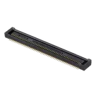
100 Position Connector Receptacle, Center Strip Contacts Surface Mount Gold
The DF40C-100DS-0.4V(51) is a board-to-board and board-to-FPC receptacle connector manufactured by Hirose Electric. It belongs to the DF40 series, a family of fine-pitch stacking connectors intended for compact, high-density interconnect applications such as mobile devices, cameras, wearables, and other space-constrained electronics. The connector functions as the receptacle (socket) half of a mating pair, designed to stack with a corresponding DF40 plug header to join two printed circuit boards, or a printed circuit board and a flexible printed circuit, in a low-profile vertical arrangement.
This particular part number represents the full-position, low-profile variant within the series, configured without a reinforcing metal fitting and without a locating boss or mechanical holddown feature, meaning it relies on the contact array itself rather than additional structural hardware for mechanical retention during reflow and handling. The connector is supplied in straight, surface-mount form and is non-polarized, so it can be inserted in either orientation relative to its mating counterpart. Contacts are arranged in parallel rows along the connector body, with gold plating in the contact mating area to ensure reliable signal continuity and resistance to oxidation over repeated use.
The series is positioned by Hirose as a general-purpose, high-speed-capable interconnect, suitable for a range of differential and single-ended signaling standards used in consumer and industrial electronics, with the broader DF40 family supporting interfaces such as USB, MIPI, SATA, and PCIe. Its low stacking height and fine contact pitch make it well suited to applications where board-to-board spacing must be minimized, such as camera modules, display modules, or stacked daughterboard architectures in handheld and wearable products. The connector is packaged on embossed carrier tape for automated pick-and-place assembly, and its construction is compliant with RoHS material restrictions.
Mechanically, the connector body is built to support repeated mating cycles typical of consumer electronics assembly and rework, while maintaining stable electrical contact under vibration and thermal cycling across its rated environmental range. As a stacking-style connector rather than a card-edge or cable-mount type, it is intended to be soldered directly to a host PCB pad pattern, with the mating plug soldered to the corresponding board or FPC, allowing the two assemblies to be joined and separated as needed during manufacturing, test, or service operations.
Spec Sheet
Identification
Part Number: DF40C-100DS-0.4V(51)
Series: DF40
Variant: "C" type — without reinforcing metal fitting
Connector Type / Configuration
Type: Receptacle (socket), board-to-board / board-to-FPC
Gender: Female
Orientation: Straight
Row Arrangement: Dual row
Polarization: Non-polarized
Locking/Retention Feature: None (no metal holddown or locating boss)
Electrical Ratings
Current Rating: Low-current signal class
Voltage Rating: Standard signal-level rating typical of fine-pitch board-to-board connectors
Applicable High-Speed Protocols: USB, MIPI, SATA, PCIe (series capability)
Transmission Rate: High-speed, multi-gigabit class (series capability)
Mechanical Specifications
Contact Pitch: Fine pitch
Mounting Pitch: Matches contact pitch
Stacking/Mated Height: Low-profile
Mounting Method: Surface mount technology (SMT)
Mating Cycles: Rated for repeated mate/unmate cycles typical of consumer electronics rework
Contact & Material Properties
Contact Material: Phosphor bronze
Contact Plating (Mating Area): Gold
Insulator Color: Black
Insulator Material: High-temperature engineering resin suitable for SMT reflow
Environmental Ratings
Operating Temperature Range: Extended consumer/industrial range
RoHS Compliance: Yes
Packaging
Packaging Format: Embossed carrier tape, reel format
Packaging Code Meaning: Suffix denotes embossed tape packaging at a standard reel quantity
Mating Compatibility
Mates With: Corresponding DF40 series plug/header connector
Application Note: Intended for mezzanine-style stacking between two PCBs or between a PCB and FPC
#DF40 #Hirose #HiroseElectric #BoardToBoard #BoardToFPC #StackingConnector #CommonPartsLibrary #Connector #SMTConnector #FinePitchConnector #MezzanineConnector #ElectronicComponents #PCBDesign #HardwareEngineering #ConnectorDatasheet #EngineeringSpec #ConsumerElectronics #HighSpeedConnector #RoHSCompliant #ComponentLibrary
Properties
DF40C-100DS-0.4V(51)
Hirose
Connectors
J
parametric-v1
Pricing & Availability
See prices from popular manufacturers for your project.
Controls
Welcome 👋
Flux accelerates your PCB design with AI.
Create your account to start using this component and bring your ideas to life.