Part Data Review and Verification
Thought for 19 mins 19 sec
Completed the review in the requested order.
1) Available part information
Part summary
Table
| Field | Value |
|---|---|
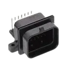
| Part | 9-6437287-9 |
| Manufacturer | TE Connectivity |
| Series | AMP SUPERSEAL 1.0 mm |
| Description | Right angle, wire-to-board, 26 position, 4 row, 3 mm centerline, gold plated, sealable, PCB header for signal |
| Connector type | Rectangular, fully shrouded header |
| Mounting | Board mount, through-hole solder |
| Orientation | Right angle |
| Contact type | Pin |
| Contact plating | Gold (Au) |
| Mating pin diameter | 1 mm |
| Signal positions | 26 |
| Extra mechanical features | 2 mounting holes present in symbol/footprint as MH1 and MH2 |
| Pitch / centerline | 3 mm [0.118 in] |
| Overall length | 39.5 mm [1.55 in] |
| Overall width | 36.5 mm [1.44 in] |
| Profile height from PCB | 27.9 mm [1.1 in] |
| Voltage rating | 250 VAC / 250 VDC |
| Nominal vehicle architectures listed | 12 / 24 / 42 / 48 / 240 V |
| Operating temperature range | -40 to 125 °C |
| IP rating | IPX7 on product page, IP67 in TE family catalog |
| Packaging | Tube, quantity 16 |
A datasheet/document URL was already set on the project, so no property update was needed.
3) Datasheet/document scan summary
I scanned the available official TE product information and TE family catalog referenced from the official product page.
Extracted metadata
Table
| Category | Extracted data |
|---|---|
| Electrical characteristics | Current up to 15 A; voltage 250 VAC / 250 VDC; insulation resistance 100 MOhm minimum at 500 VDC test; dielectric withstand 1000 VAC or 1600 VDC for 1 minute |
| Operating conditions | Operating temperature -40 to 125 °C |
| Environmental | Product page lists IPX7; catalog lists IP67 |
| Material / flammability | Housing: glass-filled PBT; TPA: glass-filled PBT; receptacle seals: silicone rubber; flammability UL 94-V0 |
| Mechanical / package dimensions | Pin header overall dimensions for 26-position version: 29.0 mm vertical length, 31.4 mm height, 39.5 mm width, 36.5 mm 90-degree length |
| Mating info | Mates with 3-1437290-8 for keying 2, 4-row, upper lock |
| Special features | Fully shrouded; sealable; integrated latch; secondary lock/TPA system; intended for harsh environments; compact high-density system |
Table
| Missing / unclear item | Status |
|---|---|
| Absolute maximum ratings | Not presented as a separate connector-style abs max table in the retrieved TE materials |
| Recommended operating conditions table | Not presented as a formal separate table; only operating temperature/voltage/current/environmental limits were available |
| Per-pin functional descriptions | Not available, because this is a passive connector and the retrieved docs did not expose a cavity numbering drawing in machine-readable form |
| Exact mounting-hole / PCB drill drawing from TE | Not recovered from the linked docs with enough certainty to verify every hole dimension directly against the footprint |
Table
| Check | Result | Notes |
|---|---|---|
| Signal pin count | Pass | Schematic has 26 numbered signal terminals |
| Mechanical holes | Pass | Schematic and footprint both include MH1 and MH2 |
| Total pad count | Pass | Footprint has 28 pads total = 26 signal + 2 mounting holes |
| Mount style | Pass | Footprint is through-hole, consistent with product data |
| Orientation family | Likely pass | Footprint is clearly for a right-angle header |
| Body envelope | Likely pass | Footprint silkscreen/fab outline is 39.5 mm x 36.5 mm, which matches TE dimensions listed on the product page |
Table
| Item | Finding | Risk |
|---|---|---|
| Pin field geometry vs stated 3 mm centerline | Footprint pads are arranged in a staggered 4-row pattern with 1.5 mm horizontal increments between adjacent pad numbers, but 3.0 mm between pads in the same row. This is plausibly consistent with TE’s 3 mm centerline claim for a 4-row connector. | Low, but should be treated as needs final drawing confirmation |
| Mounting-hole drill | Footprint uses 3.4 mm drill and 5.1 mm pad diameter for MH1/MH2. I could not directly verify these hole dimensions from the retrieved TE docs. | Medium manufacturing risk until checked against the official product drawing |
| Pin numbering / cavity numbering | The schematic symbol numbering is sequential and the footprint pad numbering is sequential. I did not recover an official TE cavity-numbering diagram to prove the physical numbering order matches the molded connector. | Medium risk for incorrect mating if numbering order is wrong |
| IP rating inconsistency across sources | Product page says IPX7 while TE catalog says IP67 | Low electrical risk, but documentation risk |
| Description text | Project description says “Connector Header Through Hole, Right Angle 26 position 0.118" (3.00 mm)” which is broadly consistent, but does not mention sealable / 4-row / SUPERSEAL family / keying variant | Low, but metadata could be improved for ordering clarity |
Table
| Area | Status |
|---|---|
| Basic symbol pin count | Good |
| Basic footprint existence | Good |
| Body size consistency | Good |
| Ordering confidence | Good on MPN |
| Manufacturing confidence | Not fully cleared until the official TE product drawing is checked for hole diameters and pin-numbering orientation |
| Board-failure risk | Main risk is pin-numbering mismatch, not electrical overstress |
- Verify cavity/pin numbering against the official TE product drawing before release.
- Verify MH1/MH2 drill diameter and spacing against the official drawing before fabrication.
- Resolve the IPX7 vs IP67 documentation discrepancy in project metadata if this matters for compliance.
If you want, I can next turn this into a clean part QA checklist for this project part.
Ask for QA checklist
Check mounting holes
Find TE drawing


Welcome 👋
Flux accelerates your PCB design with AI.
Create your account to start using this component and bring your ideas to life.