Part Data Review and Verification
19:19
Evalu.
Using Schematic Tool.
Using BOM Tool.
Using PCB Layout Tool.
Searching web for: "TE Connectivity 9-6437287-9 official datasheet PDF"
Found 1 results.
Fetching web page.
Running multiple web searches.
Found 1 results.
Found 1 results.
Found 1 results.
Running multiple web searches.
Found 1 results.
Found 1 results.
Using PCB Layout Tool.
Looking for "product description, MPN, series, connector type, position count, and any listed key features for part 9-6437287-9" in product-9-6437287-9.html
Looking for "documents and drawings listed for part 9-6437287-9 including product drawing, product specification, application specification, and catalog documents" in product-9-6437287-9.html
Looking for "technical data for SUPERSEAL 1.0 connector system relevant to 26 position cap housing assembly including current rating, voltage rating, temperature range, sealing/IP rating, flammability, contact resistance, insulation resistance, dielectric strength, and special features" in ict-superseal-cat-a4-1-1773985-2-en.pdf
Looking for "26 position cap housing assembly part numbers, housing dimensions, mating information, and cavity numbering or circuit identification" in ict-superseal-cat-a4-1-1773985-2-en.pdf
Looking for "overview and key features of the SUPERSEAL 1.0 connector system including environmental rating, applications, and major electrical or mechanical specifications" in 1308072-2-superseal-1-0.pdf
Using PCB Layout Tool.
Using Review (ERC/DRC) Tool.
Looking for "cavity numbering, pin numbering, row arrangement, or terminal numbering information for 9-6437287-9" in product-9-6437287-9.html
Looking for "mechanical dimensions including overall length, width, profile height, pitch, and mounting hole information for 9-6437287-9" in product-9-6437287-9.html
Looking for "any cavity numbering or pin numbering convention for 26 position header parts 9-6437287-9 or matching housing 3-1437290-8" in ict-superseal-cat-a4-1-1773985-2-en.pdf
Looking for "mounting hole dimensions, board hole information, or PCB layout information for the 26 position pin header 9-6437287-9" in ict-superseal-cat-a4-1-1773985-2-en.pdf
Part summary
| Field | Value |
|---|---|
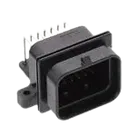
| Part | 9-6437287-9 |
| Manufacturer | TE Connectivity |
| Series | AMP SUPERSEAL 1.0 mm |
| Description | Right angle, wire-to-board, 26 position, 4 row, 3 mm centerline, gold plated, sealable, PCB header for signal |
| Connector type | Rectangular, fully shrouded header |
| Mounting | Board mount, through-hole solder |
| Orientation | Right angle |
| Contact type | Pin |
| Contact plating | Gold (Au) |
| Mating pin diameter | 1 mm |
| Signal positions | 26 |
| Extra mechanical features | 2 mounting holes present in symbol/footprint as MH1 and MH2 |
| Pitch / centerline | 3 mm [0.118 in] |
| Overall length | 39.5 mm [1.55 in] |
| Overall width | 36.5 mm [1.44 in] |
| Profile height from PCB | 27.9 mm [1.1 in] |
| Voltage rating | 250 VAC / 250 VDC |
| Nominal vehicle architectures listed | 12 / 24 / 42 / 48 / 240 V |
| Operating temperature range | -40 to 125 °C |
| IP rating | IPX7 on product page, IP67 in TE family catalog |
| Packaging | Tube, quantity 16 |
Extracted metadata
| Category | Extracted data |
|---|---|
| Electrical characteristics | Current up to 15 A; voltage 250 VAC / 250 VDC; insulation resistance 100 MOhm minimum at 500 VDC test; dielectric withstand 1000 VAC or 1600 VDC for 1 minute |
| Operating conditions | Operating temperature -40 to 125 °C |
| Environmental | Product page lists IPX7; catalog lists IP67 |
| Material / flammability | Housing: glass-filled PBT; TPA: glass-filled PBT; receptacle seals: silicone rubber; flammability UL 94-V0 |
| Mechanical / package dimensions | Pin header overall dimensions for 26-position version: 29.0 mm vertical length, 31.4 mm height, 39.5 mm width, 36.5 mm 90-degree length |
| Mating info | Mates with 3-1437290-8 for keying 2, 4-row, upper lock |
| Special features | Fully shrouded; sealable; integrated latch; secondary lock/TPA system; intended for harsh environments; compact high-density system |
What I could not extract cleanly
| Missing / unclear item | Status |
|---|---|
| Absolute maximum ratings | Not presented as a separate connector-style abs max table in the retrieved TE materials |
| Recommended operating conditions table | Not presented as a formal separate table; only operating temperature/voltage/current/environmental limits were available |
| Per-pin functional descriptions | Not available, because this is a passive connector and the retrieved docs did not expose a cavity numbering drawing in machine-readable form |
| Exact mounting-hole / PCB drill drawing from TE | Not recovered from the linked docs with enough certainty to verify every hole dimension directly against the footprint |
What matches
| Check | Result | Notes |
|---|---|---|
| Signal pin count | Pass | Schematic has 26 numbered signal terminals |
| Mechanical holes | Pass | Schematic and footprint both include MH1 and MH2 |
| Total pad count | Pass | Footprint has 28 pads total = 26 signal + 2 mounting holes |
| Mount style | Pass | Footprint is through-hole, consistent with product data |
| Orientation family | Likely pass | Footprint is clearly for a right-angle header |
| Body envelope | Likely pass | Footprint silkscreen/fab outline is 39.5 mm x 36.5 mm, which matches TE dimensions listed on the product page |
Important checks and risks
| Item | Finding | Risk |
|---|---|---|
| Pin field geometry vs stated 3 mm centerline | Footprint pads are arranged in a staggered 4-row pattern with 1.5 mm horizontal increments between adjacent pad numbers, but 3.0 mm between pads in the same row. This is plausibly consistent with TE’s 3 mm centerline claim for a 4-row connector. | Low, but should be treated as needs final drawing confirmation |
| Mounting-hole drill | Footprint uses 3.4 mm drill and 5.1 mm pad diameter for MH1/MH2. I could not directly verify these hole dimensions from the retrieved TE docs. | Medium manufacturing risk until checked against the official product drawing |
| Pin numbering / cavity numbering | The schematic symbol numbering is sequential and the footprint pad numbering is sequential. I did not recover an official TE cavity-numbering diagram to prove the physical numbering order matches the molded connector. | Medium risk for incorrect mating if numbering order is wrong |
| IP rating inconsistency across sources | Product page says IPX7 while TE catalog says IP67 | Low electrical risk, but documentation risk |
| Description text | Project description says “Connector Header Through Hole, Right Angle 26 position 0.118" (3.00 mm)” which is broadly consistent, but does not mention sealable / 4-row / SUPERSEAL family / keying variant | Low, but metadata could be improved for ordering clarity |
Current verdict
| Area | Status |
|---|---|
| Basic symbol pin count | Good |
| Basic footprint existence | Good |
| Body size consistency | Good |
| Ordering confidence | Good on MPN |
| Manufacturing confidence | Not fully cleared until the official TE product drawing is checked for hole diameters and pin-numbering orientation |
| Board-failure risk | Main risk is pin-numbering mismatch, not electrical overstress |
- Verify cavity/pin numbering against the official TE product drawing before release.
- Verify MH1/MH2 drill diameter and spacing against the official drawing before fabrication.
- Resolve the IPX7 vs IP67 documentation discrepancy in project metadata if this matters for compliance.
Ready.
Reviews

- Wirelessly connects nets on schematic. Used to organize schematics and separate functional blocks. To wirelessly connect net portals, give them same designator. #portaljharwinbarrozo43.0M
- Wirelessly connects power nets on schematic. Identical to the net portal, but with a power symbol. Used to organize schematics and separate functional blocks. To wirelessly connect power net portals, give them the same designator. #portal #powerjharwinbarrozo11.4M
- A generic fixed resistor for rapid developing circuit topology. Save precious design time by seamlessly add more information to this part (value, footprint, etc.) as it becomes available. Standard resistor values: 1.0Ω 10Ω 100Ω 1.0kΩ 10kΩ 100kΩ 1.0MΩ 1.1Ω 11Ω 110Ω 1.1kΩ 11kΩ 110kΩ 1.1MΩ 1.2Ω 12Ω 120Ω 1.2kΩ 12kΩ 120kΩ 1.2MΩ 1.3Ω 13Ω 130Ω 1.3kΩ 13kΩ 130kΩ 1.3MΩ 1.5Ω 15Ω 150Ω 1.5kΩ 15kΩ 150kΩ 1.5MΩ 1.6Ω 16Ω 160Ω 1.6kΩ 16kΩ 160kΩ 1.6MΩ 1.8Ω 18Ω 180Ω 1.8KΩ 18kΩ 180kΩ 1.8MΩ 2.0Ω 20Ω 200Ω 2.0kΩ 20kΩ 200kΩ 2.0MΩ 2.2Ω 22Ω 220Ω 2.2kΩ 22kΩ 220kΩ 2.2MΩ 2.4Ω 24Ω 240Ω 2.4kΩ 24kΩ 240kΩ 2.4MΩ 2.7Ω 27Ω 270Ω 2.7kΩ 27kΩ 270kΩ 2.7MΩ 3.0Ω 30Ω 300Ω 3.0KΩ 30KΩ 300KΩ 3.0MΩ 3.3Ω 33Ω 330Ω 3.3kΩ 33kΩ 330kΩ 3.3MΩ 3.6Ω 36Ω 360Ω 3.6kΩ 36kΩ 360kΩ 3.6MΩ 3.9Ω 39Ω 390Ω 3.9kΩ 39kΩ 390kΩ 3.9MΩ 4.3Ω 43Ω 430Ω 4.3kΩ 43KΩ 430KΩ 4.3MΩ 4.7Ω 47Ω 470Ω 4.7kΩ 47kΩ 470kΩ 4.7MΩ 5.1Ω 51Ω 510Ω 5.1kΩ 51kΩ 510kΩ 5.1MΩ 5.6Ω 56Ω 560Ω 5.6kΩ 56kΩ 560kΩ 5.6MΩ 6.2Ω 62Ω 620Ω 6.2kΩ 62KΩ 620KΩ 6.2MΩ 6.8Ω 68Ω 680Ω 6.8kΩ 68kΩ 680kΩ 6.8MΩ 7.5Ω 75Ω 750Ω 7.5kΩ 75kΩ 750kΩ 7.5MΩ 8.2Ω 82Ω 820Ω 8.2kΩ 82kΩ 820kΩ 8.2MΩ 9.1Ω 91Ω 910Ω 9.1kΩ 91kΩ 910kΩ 9.1MΩ #generics #CommonPartsLibraryjharwinbarrozo1.5M
- A generic fixed capacitor ideal for rapid circuit topology development. You can choose between polarized and non-polarized types, its symbol and the footprint will automatically adapt based on your selection. Supported options include standard SMD sizes for ceramic capacitors (e.g., 0402, 0603, 0805), SMD sizes for aluminum electrolytic capacitors, and through-hole footprints for polarized capacitors. Save precious design time by seamlessly add more information to this part (value, footprint, etc.) as it becomes available. Standard capacitor values: 1.0pF 10pF 100pF 1000pF 0.01uF 0.1uF 1.0uF 10uF 100uF 1000uF 10,000uF 1.1pF 11pF 110pF 1100pF 1.2pF 12pF 120pF 1200pF 1.3pF 13pF 130pF 1300pF 1.5pF 15pF 150pF 1500pF 0.015uF 0.15uF 1.5uF 15uF 150uF 1500uF 1.6pF 16pF 160pF 1600pF 1.8pF 18pF 180pF 1800pF 2.0pF 20pF 200pF 2000pF 2.2pF 22pF 20pF 2200pF 0.022uF 0.22uF 2.2uF 22uF 220uF 2200uF 2.4pF 24pF 240pF 2400pF 2.7pF 27pF 270pF 2700pF 3.0pF 30pF 300pF 3000pF 3.3pF 33pF 330pF 3300pF 0.033uF 0.33uF 3.3uF 33uF 330uF 3300uF 3.6pF 36pF 360pF 3600pF 3.9pF 39pF 390pF 3900pF 4.3pF 43pF 430pF 4300pF 4.7pF 47pF 470pF 4700pF 0.047uF 0.47uF 4.7uF 47uF 470uF 4700uF 5.1pF 51pF 510pF 5100pF 5.6pF 56pF 560pF 5600pF 6.2pF 62pF 620pF 6200pF 6.8pF 68pF 680pF 6800pF 0.068uF 0.68uF 6.8uF 68uF 680uF 6800uF 7.5pF 75pF 750pF 7500pF 8.2pF 82pF 820pF 8200pF 9.1pF 91pF 910pF 9100pF #generics #CommonPartsLibraryjharwinbarrozo1.5M
- A generic fixed inductor for rapid developing circuit topology. *You can now change the footprint and 3D model at the top level anytime you want. This is the power of #genericsjharwinbarrozo15.5k
- An electrical connector acting as reusable interface to a conductor and creating a point where external circuits can be connected.Terminal
- 47 kOhms ±5% 0.125W, 1/8W Chip Resistor 0805 (2012 Metric) Automotive AEC-Q200 Thick Film #forLedBlinkjharwinbarrozo1.2M
- 10uF Capacitor Aluminum Polymer 20% 16V SMD 5x5.3mm #forLedBlink #commonpartslibrary #capacitor #aluminumpolymer #radialcanjharwinbarrozo1.2M
- Yellow 595nm LED Indication - Discrete 1.7V 1206 (3216 Metric) #forLedBlinkjharwinbarrozo1.1M


Pricing & Availability
See prices from popular manufacturers for your project.
Assets

9-6437287-9
9-6437287-9 Symbol.svgDefault9-6437287-9
9-6437287-9.stp3D Model9-6437287-9
964372879.kicad_modFootprint
9-6437287-9-thumb.png
9-6437287-9-thumbThumbnailControls
Welcome 👋
Flux accelerates your PCB design with AI.
Create your account to start using this component and bring your ideas to life.