Part Datasheet Review and Analysis
1:44
Organ.
Planning.
Using Schematic Tool.
Using PCB Layout Tool.
Using BOM Tool.
Looking for "product overview part number, description, series, number of positions, number of rows, mounting orientation, contact type, pitch, and any product classification metadata" in DDEController?Action=srchrtrv&DocNm=1-1773950-7&DocType=Data%20Sheet&DocLang=English&PartCntxt=6437288-2&DocFormat=pdf
Looking for "absolute maximum ratings, current rating, voltage rating, temperature limits, dielectric withstanding voltage, insulation resistance, and any environmental limits" in DDEController?Action=srchrtrv&DocNm=1-1773950-7&DocType=Data%20Sheet&DocLang=English&PartCntxt=6437288-2&DocFormat=pdf
Looking for "recommended operating conditions, application specification, mating cycles, operating temperature, recommended pcb thickness, and any usage constraints" in DDEController?Action=srchrtrv&DocNm=1-1773950-7&DocType=Data%20Sheet&DocLang=English&PartCntxt=6437288-2&DocFormat=pdf
Looking for "pin numbering or contact numbering scheme, row numbering, mounting hole information, and any pin or contact descriptions for the 34 signal positions and mounting hardware" in DDEController?Action=srchrtrv&DocNm=1-1773950-7&DocType=Data%20Sheet&DocLang=English&PartCntxt=6437288-2&DocFormat=pdf
Looking for "mechanical dimensions including connector length width height, pcb footprint dimensions, drill sizes, pad sizes, pin pitch, row spacing, and board layout dimensions" in DDEController?Action=srchrtrv&DocNm=1-1773950-7&DocType=Data%20Sheet&DocLang=English&PartCntxt=6437288-2&DocFormat=pdf
Looking for "special features, contact plating, housing material, flammability, packaging, compliance, and any notes relevant to footprint or assembly" in DDEController?Action=srchrtrv&DocNm=1-1773950-7&DocType=Data%20Sheet&DocLang=English&PartCntxt=6437288-2&DocFormat=pdf
Using PCB Layout Tool.
Current project metadata
| Field | Value |
|---|---|
| MPN | 6437288-2 |
| Manufacturer | TE Connectivity |
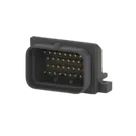
| Description | SUPER SEAL 34POS CAP ASSY |
| Family | SUPERSEAL 1.0mm |
| Part type | Connector |
| Mounting | PCB / board mount |
| Orientation | Right angle / horizontal |
| Contact type | Pin |
| Positions | 34 signal positions |
| Rows | 4 |
| Termination to PCB | Through Hole - Solder |
| Sealable | Yes |
| Color | Black |
| Packaging | Tube, qty 14 |
Schematic/footprint structure found in the project
| Item | Found |
|---|---|
| Symbol pins for signal contacts | 34 |
| Mechanical terminals/pads | 2 |
| Total symbol objects | 36 |
| Nets defined | None |
| Pad objects in footprint | 36 |
| Pin typing in symbol | All set to Unspecified |
| Explicit package/footprint name | Not exposed in current project data |
High-level characteristics
| Parameter | Value |
|---|---|
| Series | SUPERSEAL 1.0mm |
| Connector system | Wire-to-Board |
| Centerline | 3 mm |
| Contact size | 1.0 mm |
| Mating plating | Gold (Au) |
| Housing material | PBT/PET |
| Application | Signal |
| IP rating | IPX7 |
| RoHS / ELV | Compliant |
Electrical characteristics and limits
| Parameter | Value |
|---|---|
| Voltage rating | 250 V AC/DC |
| Current rating | Up to 15 A |
| Insulation resistance | 100 megohms minimum at 500 V DC |
| Dielectric withstand | 1000 V AC or 1600 V DC for 1 minute |
| Temperature range | -40 °C to +125 °C |
| Mating durability | 30 cycles max rate 600 cycles/hour |
| Contact retention | >= 58.8 N |
Current capability vs ambient temperature
| Condition | Rating |
|---|---|
| 60 °C or less, all contacts energized | 7 A/contact |
| 60 °C or less, single contact | 15 A |
| 80 °C or less, all contacts energized | 6 A/contact |
| 80 °C or less, single contact | 13 A |
| 100 °C or less, all contacts energized | 5 A/contact |
| 100 °C or less, single contact | 11 A |
| 125 °C or less, all contacts energized | 3 A/contact |
| 125 °C or less, single contact | 6 A |
Recommended operating / usage conditions
| Item | Value |
|---|---|
| Operating temperature | -40 °C to +125 °C |
| Applicable wire size | 0.5 mm² to 1.25 mm² |
| Applicable insulation diameter | phi 1.6 mm to phi 2.2 mm |
| Mating pin diameter | 1.0 mm |
| Usage note | Product drawing takes precedence for design activity |
Mechanical dimensions found
| Dimension | Value |
|---|---|
| Connector width | 45.5 mm |
| 90 degree overall length | 36.5 mm |
| Overall height | 31.4 mm |
| Related family dimensions also shown | 36.5 mm, 38.5 mm, 23.0 mm, 45.5 mm, 27.9 mm |
Package / PCB information status
| Item | Status |
|---|---|
| Recommended PCB footprint | Not found in retrieved datasheet text |
| Drill sizes | Not found |
| Pad sizes | Not found |
| Row spacing | Not found explicitly |
| Mounting hole diameter/spacing | Not found explicitly |
Pin descriptions
| Item | Result |
|---|---|
| Per-pin electrical functions | Not provided |
| Position numbering | 34 cavity arrangement identified |
| Row/keying info | Keying Type 2, 4-row, upper locking |
| Mechanical features | Mounting / flange hardware exists, but exact hole geometry was not extracted from this datasheet text |
Special features
| Feature | Detail |
|---|---|
| Environmental sealing | Sealable, IPX7 |
| Intended market | Automotive / harsh environment |
| Contact system | AMP Superseal double spring, stamped and formed |
| Lead-free note | New part numbers use tin plating and are recommended for lead-free programs |
What matches
| Check | Result |
|---|---|
| Signal position count | Pass - project has 34 numbered signal terminals, matching the datasheet |
| Additional mechanical pads | Reasonable - project includes 2 mechanical pads in addition to the 34 signal contacts |
| Right-angle connector concept | No contradiction found |
| Through-hole concept | No contradiction found |
Issues / risks found
| Severity | Finding | Why it matters |
|---|---|---|
| High | All symbol pins are typed as Unspecified | For a connector, these should generally be Passive. Leaving them unspecified can weaken ERC usefulness and hide connection mistakes. |
| High | No verified PCB land pattern dimensions available from current project data | I can see pad objects exist, but not pad size, drill diameter, or hole spacing. That means I cannot confirm manufacturability against the TE drawing. |
| High | Datasheet text did not provide a recommended PCB footprint | Since the datasheet says the product drawing takes precedence, the footprint should be checked against the official product drawing before release. |
| Medium | Symbol appears to use simple numbered terminals only | The datasheet identifies 4 rows, keying type 2, and upper locking. If the symbol does not visually communicate row/cavity orientation, there is risk of mirrored or mis-numbered harness wiring. |
| Medium | Mechanical mounting features are present but not dimension-verified | If the two mechanical pads represent hardware or flange holes, their drill and spacing must match the product drawing exactly. |
| Medium | No package name exposed in part metadata | That makes downstream verification harder and increases risk of ordering/footprint ambiguity. |
Assessment
| Category | Status |
|---|---|
| Basic metadata completeness | Good |
| Datasheet availability | Good |
| Electrical summary | Good |
| Pin-function fidelity | Limited by datasheet |
| Symbol correctness | Probably usable, but should be improved |
| Footprint correctness | Not fully verifiable from current data |
| Release readiness | Not safe to approve for manufacturing yet |
Most important fixes
| Priority | Fix |
|---|---|
| 1 | Change connector pin electrical types from Unspecified to Passive |
| 2 | Verify pad diameters, drill sizes, row spacing, and mounting-hole geometry against the official TE product drawing |
| 3 | Add clearer row/keying/orientation marking to the symbol so cavity numbering cannot be mirrored |
| 4 | Expose/store a clear package/footprint identifier in the part properties |
Ready.
Reviews

- Wirelessly connects nets on schematic. Used to organize schematics and separate functional blocks. To wirelessly connect net portals, give them same designator. #portaljharwinbarrozo43.0M
- Wirelessly connects power nets on schematic. Identical to the net portal, but with a power symbol. Used to organize schematics and separate functional blocks. To wirelessly connect power net portals, give them the same designator. #portal #powerjharwinbarrozo11.4M
- A generic fixed resistor for rapid developing circuit topology. Save precious design time by seamlessly add more information to this part (value, footprint, etc.) as it becomes available. Standard resistor values: 1.0Ω 10Ω 100Ω 1.0kΩ 10kΩ 100kΩ 1.0MΩ 1.1Ω 11Ω 110Ω 1.1kΩ 11kΩ 110kΩ 1.1MΩ 1.2Ω 12Ω 120Ω 1.2kΩ 12kΩ 120kΩ 1.2MΩ 1.3Ω 13Ω 130Ω 1.3kΩ 13kΩ 130kΩ 1.3MΩ 1.5Ω 15Ω 150Ω 1.5kΩ 15kΩ 150kΩ 1.5MΩ 1.6Ω 16Ω 160Ω 1.6kΩ 16kΩ 160kΩ 1.6MΩ 1.8Ω 18Ω 180Ω 1.8KΩ 18kΩ 180kΩ 1.8MΩ 2.0Ω 20Ω 200Ω 2.0kΩ 20kΩ 200kΩ 2.0MΩ 2.2Ω 22Ω 220Ω 2.2kΩ 22kΩ 220kΩ 2.2MΩ 2.4Ω 24Ω 240Ω 2.4kΩ 24kΩ 240kΩ 2.4MΩ 2.7Ω 27Ω 270Ω 2.7kΩ 27kΩ 270kΩ 2.7MΩ 3.0Ω 30Ω 300Ω 3.0KΩ 30KΩ 300KΩ 3.0MΩ 3.3Ω 33Ω 330Ω 3.3kΩ 33kΩ 330kΩ 3.3MΩ 3.6Ω 36Ω 360Ω 3.6kΩ 36kΩ 360kΩ 3.6MΩ 3.9Ω 39Ω 390Ω 3.9kΩ 39kΩ 390kΩ 3.9MΩ 4.3Ω 43Ω 430Ω 4.3kΩ 43KΩ 430KΩ 4.3MΩ 4.7Ω 47Ω 470Ω 4.7kΩ 47kΩ 470kΩ 4.7MΩ 5.1Ω 51Ω 510Ω 5.1kΩ 51kΩ 510kΩ 5.1MΩ 5.6Ω 56Ω 560Ω 5.6kΩ 56kΩ 560kΩ 5.6MΩ 6.2Ω 62Ω 620Ω 6.2kΩ 62KΩ 620KΩ 6.2MΩ 6.8Ω 68Ω 680Ω 6.8kΩ 68kΩ 680kΩ 6.8MΩ 7.5Ω 75Ω 750Ω 7.5kΩ 75kΩ 750kΩ 7.5MΩ 8.2Ω 82Ω 820Ω 8.2kΩ 82kΩ 820kΩ 8.2MΩ 9.1Ω 91Ω 910Ω 9.1kΩ 91kΩ 910kΩ 9.1MΩ #generics #CommonPartsLibraryjharwinbarrozo1.5M
- A generic fixed capacitor ideal for rapid circuit topology development. You can choose between polarized and non-polarized types, its symbol and the footprint will automatically adapt based on your selection. Supported options include standard SMD sizes for ceramic capacitors (e.g., 0402, 0603, 0805), SMD sizes for aluminum electrolytic capacitors, and through-hole footprints for polarized capacitors. Save precious design time by seamlessly add more information to this part (value, footprint, etc.) as it becomes available. Standard capacitor values: 1.0pF 10pF 100pF 1000pF 0.01uF 0.1uF 1.0uF 10uF 100uF 1000uF 10,000uF 1.1pF 11pF 110pF 1100pF 1.2pF 12pF 120pF 1200pF 1.3pF 13pF 130pF 1300pF 1.5pF 15pF 150pF 1500pF 0.015uF 0.15uF 1.5uF 15uF 150uF 1500uF 1.6pF 16pF 160pF 1600pF 1.8pF 18pF 180pF 1800pF 2.0pF 20pF 200pF 2000pF 2.2pF 22pF 20pF 2200pF 0.022uF 0.22uF 2.2uF 22uF 220uF 2200uF 2.4pF 24pF 240pF 2400pF 2.7pF 27pF 270pF 2700pF 3.0pF 30pF 300pF 3000pF 3.3pF 33pF 330pF 3300pF 0.033uF 0.33uF 3.3uF 33uF 330uF 3300uF 3.6pF 36pF 360pF 3600pF 3.9pF 39pF 390pF 3900pF 4.3pF 43pF 430pF 4300pF 4.7pF 47pF 470pF 4700pF 0.047uF 0.47uF 4.7uF 47uF 470uF 4700uF 5.1pF 51pF 510pF 5100pF 5.6pF 56pF 560pF 5600pF 6.2pF 62pF 620pF 6200pF 6.8pF 68pF 680pF 6800pF 0.068uF 0.68uF 6.8uF 68uF 680uF 6800uF 7.5pF 75pF 750pF 7500pF 8.2pF 82pF 820pF 8200pF 9.1pF 91pF 910pF 9100pF #generics #CommonPartsLibraryjharwinbarrozo1.5M
- A generic fixed inductor for rapid developing circuit topology. *You can now change the footprint and 3D model at the top level anytime you want. This is the power of #genericsjharwinbarrozo15.5k
- An electrical connector acting as reusable interface to a conductor and creating a point where external circuits can be connected.Terminal
- 47 kOhms ±5% 0.125W, 1/8W Chip Resistor 0805 (2012 Metric) Automotive AEC-Q200 Thick Film #forLedBlinkjharwinbarrozo1.2M
- 10uF Capacitor Aluminum Polymer 20% 16V SMD 5x5.3mm #forLedBlink #commonpartslibrary #capacitor #aluminumpolymer #radialcanjharwinbarrozo1.2M
- Yellow 595nm LED Indication - Discrete 1.7V 1206 (3216 Metric) #forLedBlinkjharwinbarrozo1.1M


Pricing & Availability
See prices from popular manufacturers for your project.
Assets

6437288-2
6437288-2 Symbol.svgDefault6437288-2
64372882.kicad_modFootprint6437288-2
6437288-2.stp3D Model
6437288-2-thumb.png
6437288-2-thumbThumbnailControls
Welcome 👋
Flux accelerates your PCB design with AI.
Create your account to start using this component and bring your ideas to life.