Part Project Metadata Review
Thought for 1 min 15 sec
I completed the review for this part project.
Step 1: Available part information
Project metadata summary
Table
| Field | Result |
|---|---|
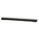
| MPN | 505110-6491 |
| Manufacturer | Molex |
| Part type | Connector |
| Series | 505110 |
| Description | Easy-On FFC/FPC Connector, 0.50 mm pitch, right-angle, bottom contact |
| Stated height in project | 1.90 mm |
| Circuits / contacts | 64 |
| Datasheet URL present | Yes |
| Datasheet URL | https://www.molex.com/pdm_docs/sd/5051106491_sd.pdf |
| Schematic terminals present | 66 total = signal pads 1 through 64, plus mounting pads MP1 and MP2 |
| Footprint asset | 5051106491.kicad_mod |
| 3D model asset | 505110-6491.stp |
A datasheet URL was already set on the part, so no web lookup or property update was needed.
Step 3: Datasheet scan and extracted metadata
Core part metadata
Table
| Parameter | Datasheet result |
|---|---|
| Product family | FFC/FPC connector |
| Series | 505110 |
| Orientation | Right-angle |
| Contact style | Bottom contact, ZIF |
| Pitch | 0.5 mm |
| Circuit count | 64 |
| Packaging | Embossed tape on reel |
| Contact plating | Gold over nickel |
| Fitting nail plating | Tin over nickel |
Table
| Parameter | Datasheet result |
|---|---|
| Voltage rating | 50 V AC (RMS) / DC |
| Current rating | 0.5 A |
| Contact resistance | 40 mΩ max |
| Insulation resistance | 100 MΩ min |
| Dielectric withstanding voltage | 250 V AC for 1 minute |
| Operating temperature | -40 to +105 °C |
Table
| Item | Datasheet result |
|---|---|
| Explicit absolute max table | Not found in the PDF extraction |
| Extracted mechanical limit | Tails and nails coplanarity: 0.1 mm max |
For this connector, the document appears to be primarily a product specification / mechanical drawing rather than an IC-style datasheet with a dedicated absolute maximum ratings table.
Recommended operating conditions
Table
| Item | Result |
|---|---|
| Explicit recommended operating conditions table | Not clearly present in the extracted PDF text |
| Usable operating range found | -40 to +105 °C |
I did find one extracted reference to a Molex series chart showing -40 to +150 °C, but that conflicts with the PDF result above, so I would not treat that as authoritative for this exact part. The PDF’s -40 to +105 °C is the safer value to use.
Pin descriptions
Table
The extracted PDF text did not provide per-pin electrical names because this is a passive connector. Sequential numbering is the main pin definition.
Package / recommended PCB dimensions extracted
Table
| Item | Datasheet result |
|---|---|
| Signal pad pitch | 0.5 ± 0.05 mm |
| Signal pad width | 0.3 ± 0.05 mm |
| Signal pad length | 1.0 ± 0.05 mm |
| Mounting pad width | 1.3 ± 0.05 mm |
| Mounting pad length | 2.0 mm class dimension appears in the recommended layout extraction |
| Row span formula | 0.5 (N-1) ± 0.05 mm |
| Other extracted recommended pattern dims | 1.55 ± 0.05 mm, 3.3 ± 0.05 mm, 2.6, 2.0 |
Table
| Feature | Result |
|---|---|
| Connector type | Easy-On FFC/FPC |
| Insertion style | ZIF |
| Contact orientation | Bottom contact |
| Mounting style | Right-angle SMT |
| Retention | Mechanical fitting nails / hold-down pads |
| Plating | Gold over nickel on contacts |
Table
| Check | Result | Notes |
|---|---|---|
| Signal pin count | Pass | Schematic has 1-64 |
| Mechanical pad count | Pass | Schematic includes MP1 and MP2 |
| Total terminal count | Pass | 66 total pads represented |
| Footprint signal pad pitch | Pass | Footprint pads are on 0.5 mm pitch |
| Footprint signal pad size | Pass | Footprint uses 0.30 mm x 1.00 mm |
| Footprint contact span | Pass | Pad 1 to 64 span is 31.5 mm, matching 0.5 x (64-1) |
| Footprint mounting pad size | Likely pass | Footprint uses 1.3 mm x 2.0 mm for MP1 and MP2 |
| Mechanical pads included | Pass | Good for manufacturability and retention |
| 3D model present | Pass | Helpful for enclosure/mechanical validation |
Table
| Issue | Severity | Why it matters |
|---|---|---|
| Project description says 1.90 mm height, but extracted PDF text returned 2.0 mm height | Medium | Could cause enclosure or mating-height mistakes and wrong part ordering if the description is used as the source of truth |
| All schematic terminals are typed Unspecified | Low to Medium | Not a fab blocker, but poor metadata quality for a reusable part |
| Schematic terminals use prefix P internally while project designator prefix is J | Low | Usually harmless in a part project, but inconsistent metadata |
| No explicit pin role metadata for mounting pads MP1 and MP2 | Medium | Could confuse downstream users; these should clearly be mechanical shield / hold-down style terminals, not generic signal pins |
| No explicit footprint-side / orientation note surfaced in the symbol metadata | Medium | Bottom-contact FFC connectors are easy to place backward in end-use designs if the symbol/documentation is not very explicit |
Table
| Area | Verdict |
|---|---|
| Pin count and pad count | Good |
| Footprint geometry vs extracted recommended layout | Looks correct |
| Manufacturing risk from footprint | Low |
| Risk of ordering / mechanical misunderstanding | Moderate |
| Most important cleanup item | Resolve the 1.90 mm vs 2.0 mm height discrepancy and make bottom-contact orientation more explicit |
- The footprint itself looks consistent with a 64-pin, 0.5 mm pitch Molex connector and includes both mounting pads MP1 and MP2.
- The biggest concern is metadata accuracy, not pad geometry:
- Height mismatch in project description vs extracted datasheet text
- Unspecified pin types
- Mounting pads not clearly labeled as mechanical
- Bottom-contact behavior not strongly encoded in part metadata
If you want, I can next turn this into a concise fix list for the part project metadata and symbol naming.
Create fix list
Check mounting pads
Verify datasheet fields


Welcome 👋
Flux accelerates your PCB design with AI.
Create your account to start using this component and bring your ideas to life.