Part Information Review and Verification

2:52
Thought for a moment
Thought for a moment
Thought for a moment
Thought for a moment
Thought for a moment
Thought for a moment
Thought for a moment
Thought for a moment
Thought for a moment
Thought for a moment
Found 1 results for 20449-001E-03 datasheet PDF I-PEX MHF4 receptacle 20449 land pattern pin.
Thought for a moment
Thought for a moment
Thought for a moment
Thought for a moment
Thought for a moment
Thought for a moment
Thought for a moment
Thought for a moment
Thought for a moment
Thought for a moment
Thought for a moment
Thought for a moment
Thought for a moment
Thought for a moment
Thought for a moment
Thought for a moment
Thought for a moment
Thought for a moment
Thought for a moment
Thought for a moment
Thought for a moment
Thought for a moment
Thought for a moment
Thought for a moment
Thought for a moment
Thought for a moment
Thought for a moment
Thought for a moment
Thought for a moment
Thought for a moment
Thought for a moment
Thought for a moment
Thought for a moment
Thought for a moment
Thought for a moment
Thought for a moment
Thought for a moment
Thought for a moment
Thought for a moment
Thought for a moment
Thought for a moment
Thought for a moment
Thought for a moment
Thought for a moment
Thought for a moment
Thought for a moment
Thought for a moment
Thought for a moment
Thought for a moment
Thought for a moment
Thought for a moment
Thought for a moment
Thought for a moment
Thought for a moment
Thought for a moment
Thought for a moment
Thought for a moment
Thought for a moment
Thought for a moment
Thought for a moment
Thought for a moment
Thought for a moment
Thought for a moment
Thought for a moment
Thought for a moment
Thought for a moment
Thought for a moment
Thought for a moment
Thought for 2 sec
Thought for a moment
Thought for a moment
Thought for a moment
Thought for a moment
Thought for a moment
Thought for a moment
Thought for a moment
Thought for a moment
Thought for a moment
Thought for a moment
Thought for a moment
Thought for a moment
Thought for a moment
Thought for a moment
Thought for a moment
Thought for a moment
Thought for a moment
Thought for a moment
Thought for a moment
Read layout.
Power In instead of RF shell/ground pads, terminal descriptions are missing, and the footprint looks plausible but could not be fully dimension-verified from the OCR-extracted datasheet.Created project doc "Part Information Review — I-PEX 20449-001E-03"
Finished working
- Project already has
Datasheet URLset to:https://www.i-pex.com/sites/default/files/downloads/pdf/2D_MHF_4_RECEPTACLE_20449_1C22.pdf - Because the property is already populated, I did not change it.
- Note: official web search found a newer/current-looking I-PEX drawing URL:
https://www.i-pex.com/sites/default/files/downloads/pdf/2D_MHF_4_RECEPTACLE_20449C22.pdfwith Rev. 22 dated 2025-09-17. Consider updating to that URL if you want the latest canonical drawing. - The datasheet/OCR extraction tools could not parse the PDF contents directly, so exact pin/land-pattern verification is limited. I used the official I-PEX web result and project data for the review.
Available project metadata
| Field | Current project value | Review |
|---|---|---|
| Manufacturer Part Number | 20449-001E-03 | Looks correct |
| Manufacturer Name | I-PEX | Looks correct |
| Part Type | Connectors | Acceptable; singular Connector may be cleaner |
| Mount | Surface Mount | Matches SMT receptacle |
| Package or Case Code | 4-SMD | Consistent with 4 footprint pads / terminals |
| Designator Prefix | J | Correct for connector |
| Datasheet URL | I-PEX PDF URL | Present; see note about newer Rev. 22 URL |
| Description | MHF4 RF coaxial receptacle, 50 Ω, up to 9 GHz, SMT | Matches available official/product info |
- Manufacturer: I-PEX
- Part: 20449-001E-03
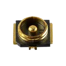
- Series/type: MHF® 4 ultra-miniature RF coaxial receptacle
- Connector style: Receptacle, male pin, snap-on mating
- Mounting: Surface-mount solder
- Characteristic impedance: 50 Ω nominal
- Frequency: up to 9 GHz
- Rated voltage: 60 V
- Operating temperature: -40 °C to +90 °C
- Mating cycles: 30 cycles
- Product page size notes: 1.2 mm max mated height, 2.0 mm × 2.0 mm SMT size
- Official drawing includes a Recommended Footprint Pattern and recommended metal mask layout with 0.12 mm mask thickness and a note that no ground, signal, or resist should be placed in the indicated keepout area.
Table
| Existing terminal UID suffix | Pin Number | Pin Type | Pin Description | Review |
|---|---|---|---|---|
4aed89b1 | 1 | Passive | Missing | Likely intended as RF center contact / signal. Passive is plausible for an RF connector pin, but the terminal should be named and described. |
3f218776 | 2 | Power In | Missing | Likely not correct for an RF coax receptacle ground/shell pad. Should probably be Ground or Passive after verifying the official drawing. |
f4cde1c7 | 3 | Power In | Missing | Likely not correct for an RF coax receptacle ground/shell pad. Should probably be Ground or Passive after verifying the official drawing. |
41254235 | 4 | Power In | Missing | Likely not correct for an RF coax receptacle ground/shell pad. Should probably be Ground or Passive after verifying the official drawing. |
- Pin count: 4 terminals in Flux, consistent with the
4-SMDpackage and footprint pad count. - Missing/weak metadata:
- Terminal designators are
~/ anonymous rather than meaningful names such asRF,GND1,GND2,GND3. Pin Descriptionis missing on all four terminals.Section,Pin Group, andPin Orientationare missing; for a small connector this is not critical, but descriptions and correct pin types are important.
- Terminal designators are
- Likely mismatch:
- Pins 2–4 are currently
Power In. For an RF coax receptacle these are very likely shell/ground mounting pads, not power inputs. Treat this as a mismatch unless the official drawing explicitly labels them otherwise.
- Pins 2–4 are currently
Table
| Pad UID suffix | Approx. position | Approx. size / shape | Review |
|---|---|---|---|
4aed89b1 | x=0, y=-0.975 mm | 0.60 × 0.55 mm rectangle | Likely center/signal pad candidate |
41254235 | x=0, y=+1.000 mm | 0.50 × 0.50 mm rectangle | Likely shell/ground pad candidate |
3f218776 | x=+1.000 mm, y=0 | custom side pad ~1.6 mm envelope | Likely shell/ground side pad |
f4cde1c7 | x=-1.000 mm, y=0 | custom side pad ~1.6 mm envelope | Likely shell/ground side pad |
- Pad count matches the schematic terminal count: 4 pads ↔ 4 terminals.
- The general layout appears consistent with an MHF4 receptacle: one center/contact pad area plus shell/ground mounting pads.
- Exact dimensional match to the official recommended footprint could not be confirmed because the PDF extraction failed. The official web result confirms the drawing has a recommended footprint pattern with dimensions including values such as 0.50, 0.60, 1.34, 1.50, 2.50, 1.58, 0.75, 0.70, 0.38, 0.54, and 1.25 mm, but the tool did not expose enough geometry to map each number unambiguously.
- The footprint currently has no explicit keepout or note corresponding to the I-PEX drawing note: no ground, signal, and resist allowed in the indicated area. If this part will be used in RF layouts, add/communicate that keepout requirement in the part documentation or footprint constraints.
- Symbol SVG exists and is marked default/thumbnail.
- KiCad footprint asset exists and is marked footprint.
- STEP 3D model exists and is marked 3D model.
- Pin type mismatch likely: Pins 2, 3, and 4 are
Power In; they should likely beGroundorPassivefor the connector shell/ground pads after checking the official drawing. - Missing terminal names/descriptions: All terminal elements are anonymous and lack
Pin Description. Suggested labels after confirmation:RF,GND1,GND2,GND3. - Datasheet URL may be outdated: Existing URL is set, but official web search found a newer/current Rev. 22 PDF at
2D_MHF_4_RECEPTACLE_20449C22.pdf. - Footprint exactness not fully verified: Pad count and general geometry look plausible, but exact pad dimensions/locations could not be fully cross-checked from the PDF extraction.
- RF layout note missing: The official drawing includes a keepout-style note for the indicated area; the part metadata/footprint should preserve that warning for users.
- Update terminal pin types/descriptions once the exact official pin assignments are confirmed from the drawing:
- Pin 1: likely
RF / Signal, Pin TypePassive, Pin DescriptionRF center contact - Pins 2–4: likely
GND / Shell, Pin TypeGroundorPassive, Pin DescriptionGround shell pad
- Pin 1: likely
- Consider updating the project
Datasheet URLto the newer official Rev. 22 PDF. - Add an
Implementation Detailsproperty noting 50 Ω RF routing and the footprint keepout/no copper/no resist restriction from the drawing.


Welcome 👋
Flux accelerates your PCB design with AI.
Create your account to start using this component and bring your ideas to life.