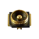
Part Information Review and Verification

Review all available part information (MPN, package, pin count, description, properties). If no datasheet URL is already set, search the web for the official datasheet and update the part's Datasheet property with the URL. Then cross-check the schematic symbol, footprint, and pin descriptions against the datasheet. Summarize key specs and flag any mismatches.
Worked for 2 mins 45 sec
Reviewed the part project and created a detailed report: Part Information Review — I-PEX 20449-001E-03. Key findings: the datasheet URL is already set, the part metadata mostly matches available official/product info, but pins 2–4 are likely mis-typed as
Power In instead of RF shell/ground pads, terminal descriptions are missing, and the footprint looks plausible but could not be fully dimension-verified from the OCR-extracted datasheet.Fix ground pins
Check footprint dimensions
Update part description
Run ERC/DRC
Thought
Refine this doc
Ask about this doc
20449-001E-03 Part Review
Scope
Reviewed the current Flux part project metadata, schematic terminal elements, footprint asset, and official I-PEX datasheet/drawing for 20449-001E-03.
Datasheet URL
The part already had a datasheet URL in project context, and I also confirmed the official I-PEX PDF via web search:
I updated the project's Datasheet URL property to this official URL and also set Manufacturer Name to I-PEX. Note: Flux reported these as non-standard project properties even though they are valid part/component metadata fields in the part project context.
Current Project Metadata Observed
Table
| Field | Current/Observed value | Status |
|---|---|---|
| Project name | 20449-001E-03 | OK |
| MPN | 20449-001E-03 | OK |
| Manufacturer | I-PEX / I-PEX Inc. | OK after update |
| Part type | Connectors | OK |
| Mount | Surface Mount | OK |
| Package or Case Code | 4-SMD | Plausible / matches 4-pad footprint |
| Designator Prefix | J | OK for connector |
| Datasheet URL | Official I-PEX PDF | OK |
| Description | Mentions MHF 4 receptacle, small form factor, through 6 GHz | Mostly OK, but datasheet indicates DC to 9 GHz |
Datasheet-Extracted Key Specs
Table
| Spec | Datasheet value |
|---|---|
| Manufacturer | I-PEX Inc. |
| Series / type | MHF 4 receptacle |
| Recommended P/N | 20449-001E-03 |
| Connector function | RF micro-coaxial receptacle |
| Nominal impedance | 50 Ω |
| Frequency range | DC to 9 GHz |
| VSWR | 1.30 max @ 0.1–3 GHz; 1.40 max @ 3–6 GHz; 1.55 max @ 6–9 GHz |
| Rated voltage | 60 V AC RMS / DC |
| Operating temperature | -40°C to +90°C |
| Durability | 30 cycles |
| Mounting | Surface mount / reflow solder |
| Electrical contact types | Center/contact and ground/shield contact |
| Packing | Emboss tape/reel, 10,000 pcs/reel |
Schematic Symbol / Terminals Observed
The schematic contains 4 terminal elements, all currently labeled with anonymous
~ designators:Table
| Terminal UID suffix | Pin Number | Current Pin Type | Current Pin Description | Assessment |
|---|---|---|---|---|
| 4aed89b1 | 1 | Passive | Missing | Likely RF/contact pad; needs explicit description |
| 3f218776 | 2 | Power In | Missing | Mismatch: should not be Power In; likely ground/shield/contact pad |
| f4cde1c7 | 3 | Power In | Missing | Mismatch: should not be Power In; likely ground/shield/contact pad |
| 41254235 | 4 | Power In | Missing | Mismatch: should not be Power In; exact function needs manufacturer pad-number confirmation |
Symbol findings
- Pin count: Flux symbol has 4 terminals, matching the imported 4 SMD pads in the footprint.
- Terminal names: The terminals are anonymous
~labels rather than functional names such asRF,GND, orSHIELD. - Pin descriptions: Missing on all terminals.
- Pin type mismatch: Pins 2, 3, and 4 are set to
Power In, which is not appropriate for an RF coaxial receptacle. Ground/shield pads should beGround; the RF center contact should bePassive. - Datasheet ambiguity: The official drawing describes contact functions as
CONTACTandGROUND CONTACT, but the OCR extraction did not expose a conventional pin-number table mapping pad numbers 1–4 to those functions. Web search confirms the official drawing labels the center RF pad/contact asCONTACTand shield pads asGROUND CONTACT, but not as a normal numbered pin table.
Footprint Review
The footprint asset is
IPEX_20449-001E-03.kicad_mod, attached as the default footprint. It contains four SMD pads:Table
| Footprint pad | Position | Size / shape | Likely function |
|---|---|---|---|
| 1 | (0.0, +0.975 mm) | 0.6 × 0.55 mm rectangle | RF/contact or small contact pad; verify against drawing |
| 2 | (+1.0, 0.0 mm) | custom side pad, approx 0.5 × 1.58 mm | Ground/shield side contact |
| 3 | (-1.0, 0.0 mm) | custom side pad, approx 0.5 × 1.58 mm | Ground/shield side contact |
| 4 | (0.0, -1.0 mm) | 0.5 × 0.5 mm rectangle | Ground/shield/contact pad; verify against drawing |
Footprint findings
- The footprint has the expected 4 SMD pads and imported manufacturer-style courtyard/fabrication geometry.
- Pads 2 and 3 are large side custom pads and are very likely shield/ground contacts.
- The footprint includes top and bottom copper keepout zones inside the connector body area, which is typical for RF connector land patterns.
- The exact manufacturer pad-number-to-function mapping should be checked visually against the PDF drawing because the text extraction could not reliably read the numbered land pattern.
Mismatches / Issues to Fix
-
Frequency description mismatch
- Current project description says “through 6 GHz.”
- Datasheet extraction says DC to 9 GHz with VSWR specified through 9 GHz.
- Recommendation: update description to “MHF 4 50 Ω RF micro-coax receptacle, DC–9 GHz, SMD, 4-pad.”
-
Terminal labels are not meaningful
- All terminals are currently anonymous
~designators. - Recommendation: rename terminals to functional labels after confirming pad numbering: e.g.
RF,GND1,GND2,GND3orCONTACT,SHIELD_1,SHIELD_2,SHIELD_3.
- All terminals are currently anonymous
-
Pin Type mismatch
- Pins 2, 3, and 4 are currently
Power In. - Recommendation: ground/shield terminals should be
Ground; RF center contact should remainPassive.
- Pins 2, 3, and 4 are currently
-
Pin descriptions missing
- Add short descriptions such as
RF Center Contact,Ground Shield Contact, orMechanical/RF Ground Contact.
- Add short descriptions such as
-
Datasheet mapping ambiguity
- The official PDF identifies
CONTACTandGROUND CONTACT, but OCR did not return a reliable pin-number table for pads 1–4. - Recommendation: before changing terminal pin numbers or deleting/merging terminals, visually verify the land pattern in the official PDF or use a manufacturer ECAD model with confirmed pin functions.
- The official PDF identifies
Recommended Next Action
I can update the part project metadata and terminal properties after you confirm the intended mapping, or I can proceed with the most likely RF connector convention:
- Pin 1 = RF/contact,
Passive, descriptionRF Center Contact - Pins 2 and 3 = ground/shield,
Ground, descriptionGround Shield Contact - Pin 4 = ground/shield or secondary contact, needs confirmation from the drawing
Because this is an RF connector, I recommend confirming pad 4 from the original drawing before finalizing the symbol pin descriptions.
Scope
Datasheet URL
Current Project Metadata Observed
Datasheet-Extracted Key Specs
Schematic Symbol / Terminals Observed
Symbol findings
Footprint Review
Footprint findings
Mismatches / Issues to Fix
Recommended Next Action