Part Review and Footprint Audit
1:59
Evalu.
Gather.
Analyzing the schematic.
Analyzing the PCB layout.
Reviewing the bill of materials.
Looking for "part number description product type and package overview" in DDEController?Action=srchrtrv&DocNm=1-1773950-7&DocType=Data%20Sheet&DocLang=English&PartCntxt=2-6437285-6&DocFormat=pdf
Looking for "electrical characteristics contact current voltage dielectric withstanding insulation resistance contact resistance" in DDEController?Action=srchrtrv&DocNm=1-1773950-7&DocType=Data%20Sheet&DocLang=English&PartCntxt=2-6437285-6&DocFormat=pdf
Looking for "recommended operating conditions temperature range application specification" in DDEController?Action=srchrtrv&DocNm=1-1773950-7&DocType=Data%20Sheet&DocLang=English&PartCntxt=2-6437285-6&DocFormat=pdf
Looking for "absolute maximum ratings current voltage temperature mechanical abuse" in DDEController?Action=srchrtrv&DocNm=1-1773950-7&DocType=Data%20Sheet&DocLang=English&PartCntxt=2-6437285-6&DocFormat=pdf
Looking for "contact arrangement pin numbering positions rows" in DDEController?Action=srchrtrv&DocNm=1-1773950-7&DocType=Data%20Sheet&DocLang=English&PartCntxt=2-6437285-6&DocFormat=pdf
Looking for "package dimensions recommended pcb layout hole size pitch row spacing board mounting dimensions" in DDEController?Action=srchrtrv&DocNm=1-1773950-7&DocType=Data%20Sheet&DocLang=English&PartCntxt=2-6437285-6&DocFormat=pdf
Looking for "special features plating material flammability UL94V-0 glow wire lead free" in DDEController?Action=srchrtrv&DocNm=1-1773950-7&DocType=Data%20Sheet&DocLang=English&PartCntxt=2-6437285-6&DocFormat=pdf
Looking for "mating and mounting dimensions header dimensions pin diameter tail length profile height from pcb" in DDEController?Action=srchrtrv&DocNm=1-1773950-7&DocType=Data%20Sheet&DocLang=English&PartCntxt=2-6437285-6&DocFormat=pdf
Analyzing the PCB layout.
Looking for "cavity numbering pattern connector face view row arrangement for 34 positions" in DDEController?Action=srchrtrv&DocNm=1-1773950-7&DocType=Data%20Sheet&DocLang=English&PartCntxt=2-6437285-6&DocFormat=pdf
Looking for "board mount mounting holes quantity and location for 2-6437285-6" in DDEController?Action=srchrtrv&DocNm=1-1773950-7&DocType=Data%20Sheet&DocLang=English&PartCntxt=2-6437285-6&DocFormat=pdf
Looking for "termination method through hole solder tail dimensions pcb hole recommendation for 2-6437285-6" in DDEController?Action=srchrtrv&DocNm=1-1773950-7&DocType=Data%20Sheet&DocLang=English&PartCntxt=2-6437285-6&DocFormat=pdf
Looking for "sealability contact plating housing material and special features for 2-6437285-6" in DDEController?Action=srchrtrv&DocNm=1-1773950-7&DocType=Data%20Sheet&DocLang=English&PartCntxt=2-6437285-6&DocFormat=pdf
1) Available part information
| Field | Value |
|---|---|
| MPN | 2-6437285-6 |
| Manufacturer | TE Connectivity |
| Part type | Connector |
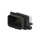
| Description | SUPER SEAL 34POS CAP ASSY H AU |
| Family / series | AMP SUPERSEAL 1.0 Connector Header |
| Mounting | Board mount, right angle, through-hole solder |
| Positions | 34 |
| Rows | 4 |
| Pitch | 3 mm / 3.5 mm |
| Contact type | Pin |
| Mating pin diameter | 1 mm |
| Plating | Gold (Au) mating area |
| Color | Black |
| Size | 45.5 mm L x 23 mm W x 21.4 mm height from PCB |
| Mounting holes | With |
| Datasheet |
Electrical and environmental data
| Category | Value |
|---|---|
| Contact current rating | 0.8 A max |
| Voltage rating | 50 VDC, 50 VAC max |
| Dielectric withstanding voltage | 500 VAC; 250 VACrms |
| Insulation resistance | 100 MΩ |
| Contact resistance | 20 mΩ |
| Operating temperature range | -40 to 140 °C |
| IP rating | JIS D0203 |
| UL flammability | UL 94V-0 |
| Sealable | Yes |
Pin / cavity information
| Item | Value |
|---|---|
| Positions | 34 |
| Row count | 4 |
| Keying | Type 2 |
| Locking | Lower |
| Mateable housing | 4-1437290-1 |
| Pin naming in current project | Numeric only: 1 through 34 |
| Functional pin descriptions in datasheet | None found |
Mechanical / package data
| Category | Value |
|---|---|
| Orientation | Right angle |
| Termination to PCB | Through Hole - Solder |
| Connector length | 45.5 mm |
| Connector width | 23 mm |
| Profile height from PCB | 21.4 mm |
| Mounting holes | 2 mounting holes |
| Centerline | 3 mm / 3.5 mm |
| Product note | Use the Product Drawing for all design activity |
Special features
| Feature | Value |
|---|---|
| Fully shrouded | Yes |
| Mating alignment | With |
| Mating retention | Locking interface |
| Board mount | Yes |
| Lead-free solder process review | Not reviewed for lead free solder process |
Findings
| Check | Result | Risk |
|---|---|---|
| Pin count | Pass - project has 34 schematic pins and 34 PCB pads | Low |
| Part orientation/type | Likely pass - project metadata matches a right-angle, board-mount, through-hole header | Low |
| Symbol structure | Fail - the symbol is built from 34 separate one-pin terminals, not a single connector symbol | Medium |
| Pin metadata | Fail - pins are undefined / Unspecified, with no connector-level pin descriptions | Medium |
| Designator convention | Mismatch - project prefix says J, but schematic elements use terminal-style prefix P | Low to Medium |
| Footprint mounting holes | Probable fail - datasheet says with mounting holes and specifically 2 mounting holes, but the visible footprint only exposes 34 pads and no clear non-signal mounting features | High |
| PCB drill / hole recommendation | Unverified - not available from the scanned catalog PDF | High |
| Pad geometry / spacing | Unverified - layout data available here did not expose full pad geometry, and the catalog PDF does not provide the full PCB land pattern | High |
Most important risks
| Priority | Issue | Why it matters |
|---|---|---|
| 1 | Missing or incorrect 2 mounting holes in the footprint | Can prevent assembly, cause mechanical misfit, poor retention, or complete board unusability |
| 2 | No verified drill sizes / hole pattern / land pattern | Can cause solderability problems or an unmanufacturable footprint |
| 3 | Symbol made from separate terminals instead of a real connector symbol | Increases risk of pin-order mistakes and incorrect net mapping |
| 4 | Connector pin metadata is incomplete | Makes review, reuse, and ordering verification harder |
Recommendation
| Action | Status |
|---|---|
| Verify the footprint against the official product drawing, not just the catalog PDF | Required |
| Confirm the footprint includes exactly 2 mounting holes in the correct locations | Required |
| Confirm plated hole diameters and row/pitch geometry from the product drawing | Required |
| Replace the current terminal-based symbol with a single connector symbol using pins 1-34 | Strongly recommended |
| Align designator behavior to connector convention J | Recommended |


Welcome 👋
Flux accelerates your PCB design with AI.
Create your account to start using this component and bring your ideas to life.
