Part Review and Footprint Audit
1:59
Evalu.
Gather.
Using Schematic Tool.
Using PCB Layout Tool.
Using BOM Tool.
Looking for "part number description product type and package overview" in DDEController?Action=srchrtrv&DocNm=1-1773950-7&DocType=Data%20Sheet&DocLang=English&PartCntxt=2-6437285-6&DocFormat=pdf
Looking for "electrical characteristics contact current voltage dielectric withstanding insulation resistance contact resistance" in DDEController?Action=srchrtrv&DocNm=1-1773950-7&DocType=Data%20Sheet&DocLang=English&PartCntxt=2-6437285-6&DocFormat=pdf
Looking for "recommended operating conditions temperature range application specification" in DDEController?Action=srchrtrv&DocNm=1-1773950-7&DocType=Data%20Sheet&DocLang=English&PartCntxt=2-6437285-6&DocFormat=pdf
Looking for "absolute maximum ratings current voltage temperature mechanical abuse" in DDEController?Action=srchrtrv&DocNm=1-1773950-7&DocType=Data%20Sheet&DocLang=English&PartCntxt=2-6437285-6&DocFormat=pdf
Looking for "contact arrangement pin numbering positions rows" in DDEController?Action=srchrtrv&DocNm=1-1773950-7&DocType=Data%20Sheet&DocLang=English&PartCntxt=2-6437285-6&DocFormat=pdf
Looking for "package dimensions recommended pcb layout hole size pitch row spacing board mounting dimensions" in DDEController?Action=srchrtrv&DocNm=1-1773950-7&DocType=Data%20Sheet&DocLang=English&PartCntxt=2-6437285-6&DocFormat=pdf
Looking for "special features plating material flammability UL94V-0 glow wire lead free" in DDEController?Action=srchrtrv&DocNm=1-1773950-7&DocType=Data%20Sheet&DocLang=English&PartCntxt=2-6437285-6&DocFormat=pdf
Looking for "mating and mounting dimensions header dimensions pin diameter tail length profile height from pcb" in DDEController?Action=srchrtrv&DocNm=1-1773950-7&DocType=Data%20Sheet&DocLang=English&PartCntxt=2-6437285-6&DocFormat=pdf
Using PCB Layout Tool.
Looking for "cavity numbering pattern connector face view row arrangement for 34 positions" in DDEController?Action=srchrtrv&DocNm=1-1773950-7&DocType=Data%20Sheet&DocLang=English&PartCntxt=2-6437285-6&DocFormat=pdf
Looking for "board mount mounting holes quantity and location for 2-6437285-6" in DDEController?Action=srchrtrv&DocNm=1-1773950-7&DocType=Data%20Sheet&DocLang=English&PartCntxt=2-6437285-6&DocFormat=pdf
Looking for "termination method through hole solder tail dimensions pcb hole recommendation for 2-6437285-6" in DDEController?Action=srchrtrv&DocNm=1-1773950-7&DocType=Data%20Sheet&DocLang=English&PartCntxt=2-6437285-6&DocFormat=pdf
Looking for "sealability contact plating housing material and special features for 2-6437285-6" in DDEController?Action=srchrtrv&DocNm=1-1773950-7&DocType=Data%20Sheet&DocLang=English&PartCntxt=2-6437285-6&DocFormat=pdf
1) Available part information
| Field | Value |
|---|---|
| MPN | 2-6437285-6 |
| Manufacturer | TE Connectivity |
| Part type | Connector |
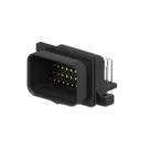
| Description | SUPER SEAL 34POS CAP ASSY H AU |
| Family / series | AMP SUPERSEAL 1.0 Connector Header |
| Mounting | Board mount, right angle, through-hole solder |
| Positions | 34 |
| Rows | 4 |
| Pitch | 3 mm / 3.5 mm |
| Contact type | Pin |
| Mating pin diameter | 1 mm |
| Plating | Gold (Au) mating area |
| Color | Black |
| Size | 45.5 mm L x 23 mm W x 21.4 mm height from PCB |
| Mounting holes | With |
| Datasheet |
Electrical and environmental data
| Category | Value |
|---|---|
| Contact current rating | 0.8 A max |
| Voltage rating | 50 VDC, 50 VAC max |
| Dielectric withstanding voltage | 500 VAC; 250 VACrms |
| Insulation resistance | 100 MΩ |
| Contact resistance | 20 mΩ |
| Operating temperature range | -40 to 140 °C |
| IP rating | JIS D0203 |
| UL flammability | UL 94V-0 |
| Sealable | Yes |
Pin / cavity information
| Item | Value |
|---|---|
| Positions | 34 |
| Row count | 4 |
| Keying | Type 2 |
| Locking | Lower |
| Mateable housing | 4-1437290-1 |
| Pin naming in current project | Numeric only: 1 through 34 |
| Functional pin descriptions in datasheet | None found |
Mechanical / package data
| Category | Value |
|---|---|
| Orientation | Right angle |
| Termination to PCB | Through Hole - Solder |
| Connector length | 45.5 mm |
| Connector width | 23 mm |
| Profile height from PCB | 21.4 mm |
| Mounting holes | 2 mounting holes |
| Centerline | 3 mm / 3.5 mm |
| Product note | Use the Product Drawing for all design activity |
Special features
| Feature | Value |
|---|---|
| Fully shrouded | Yes |
| Mating alignment | With |
| Mating retention | Locking interface |
| Board mount | Yes |
| Lead-free solder process review | Not reviewed for lead free solder process |
Findings
| Check | Result | Risk |
|---|---|---|
| Pin count | Pass - project has 34 schematic pins and 34 PCB pads | Low |
| Part orientation/type | Likely pass - project metadata matches a right-angle, board-mount, through-hole header | Low |
| Symbol structure | Fail - the symbol is built from 34 separate one-pin terminals, not a single connector symbol | Medium |
| Pin metadata | Fail - pins are undefined / Unspecified, with no connector-level pin descriptions | Medium |
| Designator convention | Mismatch - project prefix says J, but schematic elements use terminal-style prefix P | Low to Medium |
| Footprint mounting holes | Probable fail - datasheet says with mounting holes and specifically 2 mounting holes, but the visible footprint only exposes 34 pads and no clear non-signal mounting features | High |
| PCB drill / hole recommendation | Unverified - not available from the scanned catalog PDF | High |
| Pad geometry / spacing | Unverified - layout data available here did not expose full pad geometry, and the catalog PDF does not provide the full PCB land pattern | High |
Most important risks
| Priority | Issue | Why it matters |
|---|---|---|
| 1 | Missing or incorrect 2 mounting holes in the footprint | Can prevent assembly, cause mechanical misfit, poor retention, or complete board unusability |
| 2 | No verified drill sizes / hole pattern / land pattern | Can cause solderability problems or an unmanufacturable footprint |
| 3 | Symbol made from separate terminals instead of a real connector symbol | Increases risk of pin-order mistakes and incorrect net mapping |
| 4 | Connector pin metadata is incomplete | Makes review, reuse, and ordering verification harder |
Recommendation
| Action | Status |
|---|---|
| Verify the footprint against the official product drawing, not just the catalog PDF | Required |
| Confirm the footprint includes exactly 2 mounting holes in the correct locations | Required |
| Confirm plated hole diameters and row/pitch geometry from the product drawing | Required |
| Replace the current terminal-based symbol with a single connector symbol using pins 1-34 | Strongly recommended |
| Align designator behavior to connector convention J | Recommended |
Ready.
Reviews

- Wirelessly connects nets on schematic. Used to organize schematics and separate functional blocks. To wirelessly connect net portals, give them same designator. #portaljharwinbarrozo43.0M
- Wirelessly connects power nets on schematic. Identical to the net portal, but with a power symbol. Used to organize schematics and separate functional blocks. To wirelessly connect power net portals, give them the same designator. #portal #powerjharwinbarrozo11.4M
- A generic fixed resistor for rapid developing circuit topology. Save precious design time by seamlessly add more information to this part (value, footprint, etc.) as it becomes available. Standard resistor values: 1.0Ω 10Ω 100Ω 1.0kΩ 10kΩ 100kΩ 1.0MΩ 1.1Ω 11Ω 110Ω 1.1kΩ 11kΩ 110kΩ 1.1MΩ 1.2Ω 12Ω 120Ω 1.2kΩ 12kΩ 120kΩ 1.2MΩ 1.3Ω 13Ω 130Ω 1.3kΩ 13kΩ 130kΩ 1.3MΩ 1.5Ω 15Ω 150Ω 1.5kΩ 15kΩ 150kΩ 1.5MΩ 1.6Ω 16Ω 160Ω 1.6kΩ 16kΩ 160kΩ 1.6MΩ 1.8Ω 18Ω 180Ω 1.8KΩ 18kΩ 180kΩ 1.8MΩ 2.0Ω 20Ω 200Ω 2.0kΩ 20kΩ 200kΩ 2.0MΩ 2.2Ω 22Ω 220Ω 2.2kΩ 22kΩ 220kΩ 2.2MΩ 2.4Ω 24Ω 240Ω 2.4kΩ 24kΩ 240kΩ 2.4MΩ 2.7Ω 27Ω 270Ω 2.7kΩ 27kΩ 270kΩ 2.7MΩ 3.0Ω 30Ω 300Ω 3.0KΩ 30KΩ 300KΩ 3.0MΩ 3.3Ω 33Ω 330Ω 3.3kΩ 33kΩ 330kΩ 3.3MΩ 3.6Ω 36Ω 360Ω 3.6kΩ 36kΩ 360kΩ 3.6MΩ 3.9Ω 39Ω 390Ω 3.9kΩ 39kΩ 390kΩ 3.9MΩ 4.3Ω 43Ω 430Ω 4.3kΩ 43KΩ 430KΩ 4.3MΩ 4.7Ω 47Ω 470Ω 4.7kΩ 47kΩ 470kΩ 4.7MΩ 5.1Ω 51Ω 510Ω 5.1kΩ 51kΩ 510kΩ 5.1MΩ 5.6Ω 56Ω 560Ω 5.6kΩ 56kΩ 560kΩ 5.6MΩ 6.2Ω 62Ω 620Ω 6.2kΩ 62KΩ 620KΩ 6.2MΩ 6.8Ω 68Ω 680Ω 6.8kΩ 68kΩ 680kΩ 6.8MΩ 7.5Ω 75Ω 750Ω 7.5kΩ 75kΩ 750kΩ 7.5MΩ 8.2Ω 82Ω 820Ω 8.2kΩ 82kΩ 820kΩ 8.2MΩ 9.1Ω 91Ω 910Ω 9.1kΩ 91kΩ 910kΩ 9.1MΩ #generics #CommonPartsLibraryjharwinbarrozo1.5M
- A generic fixed capacitor ideal for rapid circuit topology development. You can choose between polarized and non-polarized types, its symbol and the footprint will automatically adapt based on your selection. Supported options include standard SMD sizes for ceramic capacitors (e.g., 0402, 0603, 0805), SMD sizes for aluminum electrolytic capacitors, and through-hole footprints for polarized capacitors. Save precious design time by seamlessly add more information to this part (value, footprint, etc.) as it becomes available. Standard capacitor values: 1.0pF 10pF 100pF 1000pF 0.01uF 0.1uF 1.0uF 10uF 100uF 1000uF 10,000uF 1.1pF 11pF 110pF 1100pF 1.2pF 12pF 120pF 1200pF 1.3pF 13pF 130pF 1300pF 1.5pF 15pF 150pF 1500pF 0.015uF 0.15uF 1.5uF 15uF 150uF 1500uF 1.6pF 16pF 160pF 1600pF 1.8pF 18pF 180pF 1800pF 2.0pF 20pF 200pF 2000pF 2.2pF 22pF 20pF 2200pF 0.022uF 0.22uF 2.2uF 22uF 220uF 2200uF 2.4pF 24pF 240pF 2400pF 2.7pF 27pF 270pF 2700pF 3.0pF 30pF 300pF 3000pF 3.3pF 33pF 330pF 3300pF 0.033uF 0.33uF 3.3uF 33uF 330uF 3300uF 3.6pF 36pF 360pF 3600pF 3.9pF 39pF 390pF 3900pF 4.3pF 43pF 430pF 4300pF 4.7pF 47pF 470pF 4700pF 0.047uF 0.47uF 4.7uF 47uF 470uF 4700uF 5.1pF 51pF 510pF 5100pF 5.6pF 56pF 560pF 5600pF 6.2pF 62pF 620pF 6200pF 6.8pF 68pF 680pF 6800pF 0.068uF 0.68uF 6.8uF 68uF 680uF 6800uF 7.5pF 75pF 750pF 7500pF 8.2pF 82pF 820pF 8200pF 9.1pF 91pF 910pF 9100pF #generics #CommonPartsLibraryjharwinbarrozo1.5M
- A generic fixed inductor for rapid developing circuit topology. *You can now change the footprint and 3D model at the top level anytime you want. This is the power of #genericsjharwinbarrozo15.5k
- An electrical connector acting as reusable interface to a conductor and creating a point where external circuits can be connected.Terminal
- 47 kOhms ±5% 0.125W, 1/8W Chip Resistor 0805 (2012 Metric) Automotive AEC-Q200 Thick Film #forLedBlinkjharwinbarrozo1.2M
- 10uF Capacitor Aluminum Polymer 20% 16V SMD 5x5.3mm #forLedBlink #commonpartslibrary #capacitor #aluminumpolymer #radialcanjharwinbarrozo1.2M
- Yellow 595nm LED Indication - Discrete 1.7V 1206 (3216 Metric) #forLedBlinkjharwinbarrozo1.1M


Pricing & Availability
See prices from popular manufacturers for your project.
Assets

2-6437285-6-thumb.png
2-6437285-6-thumb
2-6437285-6
2-6437285-6 Symbol.svgDefault2-6437285-6
2-6437285-6.stp3D Model2-6437285-6
264372856.kicad_modFootprintControls
Welcome 👋
Flux accelerates your PCB design with AI.
Create your account to start using this component and bring your ideas to life.