Part Review and Datasheet Analysis
1:04
Analyzing the schematic.
Reviewing the bill of materials.
Analyzing the PCB layout.
Looking for "part overview description order number and general metadata" in 311010040?display=pdf
Looking for "electrical characteristics current voltage contact resistance insulation resistance dielectric withstanding voltage" in 311010040?display=pdf
Looking for "absolute maximum ratings or maximum environmental and electrical limits" in 311010040?display=pdf
Looking for "recommended operating conditions operating temperature and application conditions" in 311010040?display=pdf
Looking for "pin count circuit count contacts and pin numbering or terminal assignment" in 311010040?display=pdf
Looking for "package dimensions mechanical dimensions pitch overall height overall width length drill size recommended pcb layout" in 311010040?display=pdf
Looking for "special features polarization plating material flammability glow wire and application notes" in 311010040?display=pdf
Assess.
Evalu.
Part information review
| Field | Result |
|---|---|
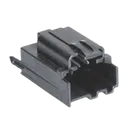
| MPN | 0311010040 |
| Manufacturer | Molex |
| Description | H-DAC 64 2.54 mm 4 Way Vertical Header Assembly, Polarization A |
| Part type | Connectors |
| Mount | Vertical, Through Hole |
| Circuits / pin count | 4 |
| Pitch | 2.54 mm |
| Datasheet URL | Present in project properties |
| Schematic implementation | Four separate terminals: 1, 2, 3, 4 |
| Footprint implementation | 4 plated through-hole pins plus 2 non-plated locating holes, with 3D model attached |
Datasheet metadata summary
| Category | Datasheet findings |
|---|---|
| Electrical characteristics | 3 A current, 500 V voltage, 10 mΩ max contact resistance, 1000 MΩ min insulation resistance, 1500 V AC/minute dielectric withstanding voltage |
| Absolute maximum / limits | No formal absolute maximum ratings table was found in the available PDF page content; the clearest published limit found was operating temperature |
| Recommended operating conditions | -40 °C to +100 °C, PCB thickness 1.57 ± 0.17 mm, through-hole mounting |
| Pin descriptions | 4 circuits / 4 contacts confirmed, but no per-pin functional descriptions were provided in the available datasheet content |
| Mechanical / package dimensions | Overall 21.7 mm L, 14.23 mm W, 12.88 mm H; dimensions shown include A = 14.23 mm, B = 16.20 mm, C = 3.18 mm, D = 14.68 mm |
| Recommended PCB layout | 4x Ø1.04 ± 0.08 mm plated holes on 2.54 mm pitch, plus 2x Ø2.25 ± 0.08 mm locating holes |
| Special features | Polarization A, tin plating on mating and termination, nickel underplate, modified polystyrene resin, Glow-Wire: No, Flammability: No |
Symbol and footprint cross-check
| Check | Result | Risk |
|---|---|---|
| Electrical pin count | Symbol has 4 terminals; datasheet specifies 4 circuits | No mismatch found |
| Pin numbering | Symbol terminals are numbered 1-4; footprint pads are 1-4 | No mismatch found |
| Pitch | Footprint uses 2.54 mm spacing | Matches datasheet |
| Drill size | Footprint uses 1.04 mm drill for pins | Matches datasheet |
| Locating holes | Footprint includes 2x 2.25 mm NPTH locating holes | Matches datasheet |
| Pin 1 marking | Footprint uses rectangular pad on pin 1 | Good, helps assembly/orientation |
| 3D asset | 3D model is present | Good |
| Symbol semantics | The schematic uses four generic terminals rather than a single connector symbol body | Usable, but increases risk of human wiring/orientation mistakes in larger designs |
| Pin electrical types | Symbol pins are marked Unspecified | Low manufacturing risk, but weaker ERC behavior |
Issues flagged
| Issue | Severity | Why it matters |
|---|---|---|
| Generic multi-terminal symbol instead of a connector body | Medium | Makes polarization/orientation less obvious and can cause wiring mistakes during design review or reuse |
| Pin types are Unspecified | Low | Can reduce schematic/ERC quality, though it should not directly cause fab failure |
| Datasheet source appears to expose only limited catalog content | Medium | Some metadata is available, but the source does not expose a rich pin-function table or a full formal ratings structure |
- I found no hard mismatch between the implemented footprint and the published mechanical recommendation.
- The footprint appears manufacturing-safe based on the available Molex data.
- The main concern is the symbol quality, not the footprint: using separate generic terminals instead of a proper polarized connector symbol makes this part easier to misuse in a real design.
Ready.
Reviews

- Wirelessly connects nets on schematic. Used to organize schematics and separate functional blocks. To wirelessly connect net portals, give them same designator. #portaljharwinbarrozo43.0M
- Wirelessly connects power nets on schematic. Identical to the net portal, but with a power symbol. Used to organize schematics and separate functional blocks. To wirelessly connect power net portals, give them the same designator. #portal #powerjharwinbarrozo11.4M
- A generic fixed resistor ideal for rapid circuit topology development. Its footprint automatically adapts based on the selected package case code—supporting 0402, 0603, 0805, 1203, and many other standard SMD packages, as well as axial horizontal and vertical configurations. Save precious design time by seamlessly add more information to this part (value, footprint, etc.) as it becomes available. Standard resistor values: 1.0 ohm, 10 ohm, 100 ohm, 1.0k ohm, 10k ohm, 100k ohm, 1.0M ohm 1.1 ohm, 11 ohm, 110 ohm, 1.1k ohm, 11k ohm, 110k ohm, 1.1M ohm 1.2 ohm, 12 ohm, 120 ohm, 1.2k ohm, 12k ohm, 120k ohm, 1.2M ohm 1.3 ohm, 13 ohm, 130 ohm, 1.3k ohm, 13k ohm, 130k ohm, 1.3M ohm 1.5 ohm, 15 ohm, 150 ohm, 1.5k ohm, 15k ohm, 150k ohm, 1.5M ohm 1.6 ohm, 16 ohm, 160 ohm, 1.6k ohm, 16k ohm, 160k ohm, 1.6M ohm 1.8 ohm, 18 ohm, 180 ohm, 1.8K ohm, 18k ohm, 180k ohm, 1.8M ohm 2.0 ohm, 20 ohm, 200 ohm, 2.0k ohm, 20k ohm, 200k ohm, 2.0M ohm 2.2 ohm, 22 ohm, 220 ohm, 2.2k ohm, 22k ohm, 220k ohm, 2.2M ohm 2.4 ohm, 24 ohm, 240 ohm, 2.4k ohm, 24k ohm, 240k ohm, 2.4M ohm 2.7 ohm, 27 ohm, 270 ohm, 2.7k ohm, 27k ohm, 270k ohm, 2.7M ohm 3.0 ohm, 30 ohm, 300 ohm, 3.0K ohm, 30K ohm, 300K ohm, 3.0M ohm 3.3 ohm, 33 ohm, 330 ohm, 3.3k ohm, 33k ohm, 330k ohm, 3.3M ohm 3.6 ohm, 36 ohm, 360 ohm, 3.6k ohm, 36k ohm, 360k ohm, 3.6M ohm 3.9 ohm, 39 ohm, 390 ohm, 3.9k ohm, 39k ohm, 390k ohm, 3.9M ohm 4.3 ohm, 43 ohm, 430 ohm, 4.3k ohm, 43K ohm, 430K ohm, 4.3M ohm 4.7 ohm, 47 ohm, 470 ohm, 4.7k ohm, 47k ohm, 470k ohm, 4.7M ohm 5.1 ohm, 51 ohm, 510 ohm, 5.1k ohm, 51k ohm, 510k ohm, 5.1M ohm 5.6 ohm, 56 ohm, 560 ohm, 5.6k ohm, 56k ohm, 560k ohm, 5.6M ohm 6.2 ohm, 62 ohm, 620 ohm, 6.2k ohm, 62K ohm, 620K ohm, 6.2M ohm 6.8 ohm, 68 ohm, 680 ohm, 6.8k ohm, 68k ohm, 680k ohm, 6.8M ohm 7.5 ohm, 75 ohm, 750 ohm, 7.5k ohm, 75k ohm, 750k ohm, 7.5M ohm 8.2 ohm, 82 ohm, 820 ohm, 8.2k ohm, 82k ohm, 820k ohm, 8.2M ohm 9.1 ohm, 91 ohm, 910 ohm, 9.1k ohm, 91k ohm, 910k ohm, 9.1M ohm #generics #CommonPartsLibraryjharwinbarrozo1.5M
- A generic fixed capacitor ideal for rapid circuit topology development. You can choose between polarized and non-polarized types, its symbol and the footprint will automatically adapt based on your selection. Supported options include standard SMD sizes for ceramic capacitors (e.g., 0402, 0603, 0805), SMD sizes for aluminum electrolytic capacitors, and through-hole footprints for polarized capacitors. Save precious design time by seamlessly add more information to this part (value, footprint, etc.) as it becomes available. Standard capacitor values: 1.0pF, 10pF, 100pF, 1000pF, 0.01uF, 0.1uF, 1.0uF, 10uF, 100uF, 1000uF, 10000uF 1.1pF, 11pF, 110pF, 1100pF 1.2pF, 12pF, 120pF, 1200pF 1.3pF, 13pF, 130pF, 1300pF 1.5pF, 15pF, 150pF, 1500pF, 0.015uF, 0.15uF, 1.5uF, 15uF, 150uF, 1500uF 1.6pF, 16pF, 160pF, 1600pF 1.8pF, 18pF, 180pF, 1800pF 2.0pF, 20pF, 200pF, 2000pF 2.2pF, 22pF, 220pF, 2200pF, 0.022uF, 0.22uF, 2.2uF, 22uF, 220uF, 2200uF 2.4pF, 24pF, 240pF, 2400pF 2.7pF, 27pF, 270pF, 2700pF 3.0pF, 30pF, 300pF, 3000pF 3.3pF, 33pF, 330pF, 3300pF, 0.033uF, 0.33uF, 3.3uF, 33uF, 330uF, 3300uF 3.6pF, 36pF, 360pF, 3600pF 3.9pF, 39pF, 390pF, 3900pF 4.3pF, 43pF, 430pF, 4300pF 4.7pF, 47pF, 470pF, 4700pF, 0.047uF, 0.47uF, 4.7uF, 47uF, 470uF, 4700uF 5.1pF, 51pF, 510pF, 5100pF 5.6pF, 56pF, 560pF, 5600pF 6.2pF, 62pF, 620pF, 6200pF 6.8pF, 68pF, 680pF, 6800pF, 0.068uF, 0.68uF, 6.8uF, 68uF, 680uF, 6800uF 7.5pF, 75pF, 750pF, 7500pF 8.2pF, 82pF, 820pF, 8200pF 9.1pF, 91pF, 910pF, 9100pF #generics #CommonPartsLibraryjharwinbarrozo1.5M
- A generic fixed inductor suitable for rapid circuit topology development. The footprint automatically adapts based on the selected package, supporting standard SMD sizes (e.g., 0402, 0603, 0805) as well as well-known inductor packages such as SDR1806, PA4320, SRN6028, and SRR1260. Standard inductor values: 1.0 nH, 10 nH, 100 nH, 1.0 µH, 10 µH, 100 µH, 1.0 mH 1.2 nH, 12 nH, 120 nH, 1.2 µH, 12 µH, 120 µH, 1.2 mH 1.5 nH, 15 nH, 150 nH, 1.5 µH, 15 µH, 150 µH, 1.5 mH 1.8 nH, 18 nH, 180 nH, 1.8 µH, 18 µH, 180 µH, 1.8 mH 2.2 nH, 22 nH, 220 nH, 2.2 µH, 22 µH, 220 µH, 2.2 mH 2.7 nH, 27 nH, 270 nH, 2.7 µH, 27 µH, 270 µH, 2.7 mH 3.3 nH, 33 nH, 330 nH, 3.3 µH, 33 µH, 330 µH, 3.3 mH 3.9 nH, 39 nH, 390 nH, 3.9 µH, 39 µH, 390 µH, 3.9 mH 4.7 nH, 47 nH, 470 nH, 4.7 µH, 47 µH, 470 µH, 4.7 mH 5.6 nH, 56 nH, 560 nH, 5.6 µH, 56 µH, 560 µH, 5.6 mH 6.8 nH, 68 nH, 680 nH, 6.8 µH, 68 µH, 680 µH, 6.8 mH 8.2 nH, 82 nH, 820 nH, 8.2 µH, 82 µH, 820 µH, 8.2 mH #generics #CommonPartsLibraryjharwinbarrozo15.6k
- An electrical connector acting as reusable interface to a conductor and creating a point where external circuits can be connected.Terminal
- 47 kOhms ±5% 0.125W, 1/8W Chip Resistor 0805 (2012 Metric) Automotive AEC-Q200 Thick Film #forLedBlinkjharwinbarrozo1.2M
- 10uF Capacitor Aluminum Polymer 20% 16V SMD 5x5.3mm #forLedBlink #commonpartslibrary #capacitor #aluminumpolymer #radialcanjharwinbarrozo1.2M
- Yellow 595nm LED Indication - Discrete 1.7V 1206 (3216 Metric) #forLedBlinkjharwinbarrozo1.1M


0311010040
Properties
0311010040
Molex
Connectors
J
Vertical
Pricing & Availability
See prices from popular manufacturers for your project.
Assets

0311010040
0311010040 Symbol.svgDefault0311010040
0311010040.kicad_modFootprint
0311010040-thumb.png
0311010040-thumbThumbnail0311010040
0311010040.stp3D ModelControls
Welcome 👋
Flux accelerates your PCB design with AI.
Create your account to start using this component and bring your ideas to life.