Thiết Kế Mạch PCB Drone
Hiện tại tôi muốn dùng web Flux.ai để thiết kế mạch test drone sử dụng STM32F4i tôi muốn dùng web Flux.ai để thiết kế mạch test drone PCB thông qua hình ảnh bên trên với những mạch có sẵn sử dụng STM32F407 Discovery, MPU6050, QMC5883L, 2 LED, Đầu St-Link và PPM Reader, đầu cắm Power, cùng với các giao thức truyền thông PPM, UART, I2C, PWM. Bạn hãy giúp tôi tính toán và thiết kế nguyên lí mạch Schematic trên Flux và từ đó sắp xếp các linh kiện để thành một board PCB 2 lớp hoàn chỉnh nhất
323 days
0:28
Project
Để có thể tính toán và thiết kế sơ đồ mạch (schematic) cũng như bố trí linh kiện cho board PCB 2 lớp phù hợp, tôi sẽ đặt 5 câu hỏi. Hãy trả lời từng câu hỏi một hoặc cho phép tôi giả định các giá trị điển hình nếu bạn không có yêu cầu cụ thể.
Câu hỏi 1:
Bạn có yêu cầu đặc biệt nào về hệ thống cấp nguồn không? Ví dụ, bạn muốn mạch hoạt động hoàn toàn ở 3.3V (phù hợp với STM32F407) hay bạn cần thêm một nguồn 5V cho các linh kiện khác (như LED, St-Link, hoặc các cảm biến)?
Bạn có yêu cầu đặc biệt nào về hệ thống cấp nguồn không? Ví dụ, bạn muốn mạch hoạt động hoàn toàn ở 3.3V (phù hợp với STM32F407) hay bạn cần thêm một nguồn 5V cho các linh kiện khác (như LED, St-Link, hoặc các cảm biến)?
Dual voltage setup
Add auxiliary 5V
3.3V main and 5V rail
Require both supplies
323 days
Ready.
C3
Capacitance
0.1u F
C4
Capacitance
0.01u F
IC1
Reviews

- Wirelessly connects nets on schematic. Used to organize schematics and separate functional blocks. To wirelessly connect net portals, give them same designator. #portaljharwinbarrozo43.0M
- Wirelessly connects power nets on schematic. Identical to the net portal, but with a power symbol. Used to organize schematics and separate functional blocks. To wirelessly connect power net portals, give them the same designator. #portal #powerjharwinbarrozo11.4M
- A generic fixed resistor for rapid developing circuit topology. Save precious design time by seamlessly add more information to this part (value, footprint, etc.) as it becomes available. Standard resistor values: 1.0Ω 10Ω 100Ω 1.0kΩ 10kΩ 100kΩ 1.0MΩ 1.1Ω 11Ω 110Ω 1.1kΩ 11kΩ 110kΩ 1.1MΩ 1.2Ω 12Ω 120Ω 1.2kΩ 12kΩ 120kΩ 1.2MΩ 1.3Ω 13Ω 130Ω 1.3kΩ 13kΩ 130kΩ 1.3MΩ 1.5Ω 15Ω 150Ω 1.5kΩ 15kΩ 150kΩ 1.5MΩ 1.6Ω 16Ω 160Ω 1.6kΩ 16kΩ 160kΩ 1.6MΩ 1.8Ω 18Ω 180Ω 1.8KΩ 18kΩ 180kΩ 1.8MΩ 2.0Ω 20Ω 200Ω 2.0kΩ 20kΩ 200kΩ 2.0MΩ 2.2Ω 22Ω 220Ω 2.2kΩ 22kΩ 220kΩ 2.2MΩ 2.4Ω 24Ω 240Ω 2.4kΩ 24kΩ 240kΩ 2.4MΩ 2.7Ω 27Ω 270Ω 2.7kΩ 27kΩ 270kΩ 2.7MΩ 3.0Ω 30Ω 300Ω 3.0KΩ 30KΩ 300KΩ 3.0MΩ 3.3Ω 33Ω 330Ω 3.3kΩ 33kΩ 330kΩ 3.3MΩ 3.6Ω 36Ω 360Ω 3.6kΩ 36kΩ 360kΩ 3.6MΩ 3.9Ω 39Ω 390Ω 3.9kΩ 39kΩ 390kΩ 3.9MΩ 4.3Ω 43Ω 430Ω 4.3kΩ 43KΩ 430KΩ 4.3MΩ 4.7Ω 47Ω 470Ω 4.7kΩ 47kΩ 470kΩ 4.7MΩ 5.1Ω 51Ω 510Ω 5.1kΩ 51kΩ 510kΩ 5.1MΩ 5.6Ω 56Ω 560Ω 5.6kΩ 56kΩ 560kΩ 5.6MΩ 6.2Ω 62Ω 620Ω 6.2kΩ 62KΩ 620KΩ 6.2MΩ 6.8Ω 68Ω 680Ω 6.8kΩ 68kΩ 680kΩ 6.8MΩ 7.5Ω 75Ω 750Ω 7.5kΩ 75kΩ 750kΩ 7.5MΩ 8.2Ω 82Ω 820Ω 8.2kΩ 82kΩ 820kΩ 8.2MΩ 9.1Ω 91Ω 910Ω 9.1kΩ 91kΩ 910kΩ 9.1MΩ #generics #CommonPartsLibraryjharwinbarrozo1.5M
- A generic fixed capacitor ideal for rapid circuit topology development. You can choose between polarized and non-polarized types, its symbol and the footprint will automatically adapt based on your selection. Supported options include standard SMD sizes for ceramic capacitors (e.g., 0402, 0603, 0805), SMD sizes for aluminum electrolytic capacitors, and through-hole footprints for polarized capacitors. Save precious design time by seamlessly add more information to this part (value, footprint, etc.) as it becomes available. Standard capacitor values: 1.0pF 10pF 100pF 1000pF 0.01uF 0.1uF 1.0uF 10uF 100uF 1000uF 10,000uF 1.1pF 11pF 110pF 1100pF 1.2pF 12pF 120pF 1200pF 1.3pF 13pF 130pF 1300pF 1.5pF 15pF 150pF 1500pF 0.015uF 0.15uF 1.5uF 15uF 150uF 1500uF 1.6pF 16pF 160pF 1600pF 1.8pF 18pF 180pF 1800pF 2.0pF 20pF 200pF 2000pF 2.2pF 22pF 20pF 2200pF 0.022uF 0.22uF 2.2uF 22uF 220uF 2200uF 2.4pF 24pF 240pF 2400pF 2.7pF 27pF 270pF 2700pF 3.0pF 30pF 300pF 3000pF 3.3pF 33pF 330pF 3300pF 0.033uF 0.33uF 3.3uF 33uF 330uF 3300uF 3.6pF 36pF 360pF 3600pF 3.9pF 39pF 390pF 3900pF 4.3pF 43pF 430pF 4300pF 4.7pF 47pF 470pF 4700pF 0.047uF 0.47uF 4.7uF 47uF 470uF 4700uF 5.1pF 51pF 510pF 5100pF 5.6pF 56pF 560pF 5600pF 6.2pF 62pF 620pF 6200pF 6.8pF 68pF 680pF 6800pF 0.068uF 0.68uF 6.8uF 68uF 680uF 6800uF 7.5pF 75pF 750pF 7500pF 8.2pF 82pF 820pF 8200pF 9.1pF 91pF 910pF 9100pF #generics #CommonPartsLibraryjharwinbarrozo1.5M
- A generic fixed inductor for rapid developing circuit topology. *You can now change the footprint and 3D model at the top level anytime you want. This is the power of #genericsjharwinbarrozo15.5k
- An electrical connector acting as reusable interface to a conductor and creating a point where external circuits can be connected.Terminal
- 47 kOhms ±5% 0.125W, 1/8W Chip Resistor 0805 (2012 Metric) Automotive AEC-Q200 Thick Film #forLedBlinkjharwinbarrozo1.2M
- 10uF Capacitor Aluminum Polymer 20% 16V SMD 5x5.3mm #forLedBlink #commonpartslibrary #capacitor #aluminumpolymer #radialcanjharwinbarrozo1.2M
- Yellow 595nm LED Indication - Discrete 1.7V 1206 (3216 Metric) #forLedBlinkjharwinbarrozo1.1M


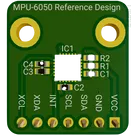
This is the MPU-6050 IMU reference design. This reference design has a basic I2C circuit for communication built according to the manufacturer's recommendations
#IMU #MPU-6050 #I2C #referenceDesign #tdk #template #reference-design
Pricing & Availability
Distributor | Qty 1 |
|---|---|
Digi-Key | $4.63–$7.16 |
LCSC | $7.77 |
Mouser | $8.59 |
Assets

MPU-6050 Reference Design.png
MPU-6050 Reference DesignThumbnailControls
Welcome 👋
Flux helps you build PCBs faster with an AI teammate!
Create your account to collaborate, stay updated, fork your own version, and get instant answers from our AI agent.
ziondido
copilot
ziondido
copilot
-
Gather Components: Ensure you have the MPU-6050 module, an ATmega microcontroller (e.g., ATmega328P), a breadboard, jumper wires, pull-up resistors (if not using Arduino which has built-in), and a power source.
-
Circuit Connections:
- Connect the MPU-6050's VCC to the ATmega328P's 3.3V output to power the sensor. If your ATmega system operates at 5V, use a voltage regulator to provide 3.3V to the MPU-6050.
- Connect the GND of the MPU-6050 to the GND of the ATmega328P.
- Connect SDA and SCL of the MPU-6050 to the ATmega328P's SDA (PC4) and SCL (PC5) pins, respectively.
- Attach pull-up resistors (e.g., 4.7kΩ) between SDA, SCL lines, and the 3.3V power line if they're not already implemented in your system.
- If using MPU-6050's interrupt features, connect the INT pin to one of the external interrupt pins on the ATmega (e.g., PD2 for INT0).
2. Software Development-
Set up Development Environment: Install the necessary software for coding and uploading firmware to your ATmega chip. This could be the Arduino IDE if you're using an Arduino bootloader or AVR-GCC for raw C programming.
-
Code Writing:
- Initialize I2C communication in your microcontroller's firmware.
- Write functions to read from and write to the MPU-6050's registers.
- Implement algorithms to interpret the accelerometer and gyroscope data, such as converting raw data to understandable units (e.g., g's for acceleration, degrees per second for rotation).
-
Library Usage: Optionally, for Arduino, leverage existing libraries like "Wire.h" for I2C communication and "MPU6050.h" (if available) to simplify interactions with the sensor.
3. Testing and Debugging-
Initial Test: Upload the firmware to the ATmega and power up the circuit. Check for basic signs of life (LEDs, serial output).
-
Functionality Test: Run a simple program that outputs MPU-6050 data to a serial monitor. Observe if the accelerometer and gyroscope readings change with the sensor's orientation and movement.
-
Debugging: If the data does not appear or seems incorrect, double-check your connections, review your code for logical errors, and ensure correct I2C addresses and register values are used.
-
Iterate: Modify your firmware and hardware setup based on test results until your project meets the desired functional requirements.
4. Finalizationziondido
copilot
-
ATmega Microcontroller:
- Search for "ATmega328P" in the component library. If this specific model isn't available, look for an equivalent ATmega microcontroller that meets your project's needs.
- Add the microcontroller to your schematic.
-
Power Supply:
- You will need a 3.3V power supply for the MPU-6050. If your ATmega microcontroller operates at 5V and you don't have a direct 3.3V supply, search for a "3.3V regulator" component and add it to your schematic for voltage regulation.
-
Pull-up Resistors for I2C:
- Typically, 4.7kΩ resistors are used as pull-up resistors on the SDA and SCL lines for I2C communication. Add two resistors with a value of 4.7kΩ (you might find it as "4.7k ohm resistor") to your schematic.
-
Connections to ATmega:
- Since we are considering an ATmega328P (or a similar pinout microcontroller), you'll find the I2C pins labeled as SDA (PC4) and SCL (PC5). These would be connected to the respective SDA and SCL pins of the MPU-6050.
- Don't forget to connect VCC (to 3.3V), GND, and if you're using interrupts, the external interrupt pin on the ATmega to the MPU-6050's INT pin.
-
Additional Components:
- For more complete circuitry, consider adding decoupling capacitors near the power supply pins of both the MPU-6050 and the ATmega microcontroller. A value like 0.1μF is commonly used for this purpose. Add two 0.1μF capacitors to your schematic.
How to Perform These Actions in Flux.ai: