PCB Design Assistance

1:11

General (prev)
Chat History
Project
PCB Layout
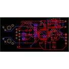
아래 표는 W5500(IC32) 주변 전원핀 디커플링 커패시터까지의 2D 거리(mm) 계산 결과입니다. 가이드라인인 “1 mm 이내”와 비교하였습니다.

Table


커패시터위치 (X,Y) mmIC32 위치 (8, 0) mmΔX (mm)ΔY (mm)거리 (mm)권장 여부 (≤ 1 mm)
C11(8.963, –1.761)(8, 0)+0.963–1.7612.00×
C34(0.8, 0)(8, 0)–7.200.007.20×
C28(17, –11)(8, 0)+9.00–11.0014.21×
C47(0.8, 8.3)(8, 0)–7.20+8.3010.99×
C59(0.8, 4)(8, 0)–7.20+4.008.24×
C18(18.174, 3.137)(8, 0)+10.174+3.13710.65×
C68(17, –6.8)(8, 0)+9.00–6.8011.28×
C11(8.963, –1.761)(8, 0)+0.963–1.7612.00×
결론:
  • 모든 디커플링 캐패시터가 IC32 전원 핀에 1 mm 이하로 가까이 배치되지 않았습니다.
  • 특히 C11(≈2 mm)이 가장 가깝지만, 권장 ≤ 1 mm를 크게 벗어나 있습니다.
  • 나머지 캐패시터는 7 mm 이상 떨어져 있어, 디커플링 성능(ESL/ESR 저감 및 전기적 안정성)에 악영향을 줄 수 있습니다.
회로 무결성을 위해:
  • 각 전원 핀(C34, AVDD, VDD 등)에 인접 디커플링을 0.5 ~ 1 mm 이내로 재배치하세요.
  • IC32 주변에 최소 두 개 이상의 고주파/저주파 병렬 디커플링을 핀 바로 옆에 근접 배치해 EMI/전압 강하를 억제해야 합니다.
  • DRC에서 “missing decoupling_caps” 경고가 없는지 다시 확인하고, 필요 시 Auto-Layout 규칙으로 “1 mm 이내” 규칙을 추가하세요.
244 days

Ready.


M1
R52
Resistance
10k Ω
PMODE0
RX
R31
Resistance
10k Ω
ACTLED
C3
Capacitance
6.8n F
R71
Resistance
10k Ω
R73
Resistance
10k Ω
R62
Resistance
33 Ω
RX
C11
Capacitance
0.1u F
R21
Resistance
33 Ω
R26
Resistance
10k Ω
C1
Capacitance
22n F
C28
Capacitance
0.1u F
R27
Resistance
10k Ω
SC
R69
Resistance
33 Ω
TX_N
EXRES1
TX_P
PMODE1
R6
Resistance
49.9 Ω
C18
Capacitance
0.1u F
C59
Capacitance
10u F
Voltage
16 V
C34
Capacitance
0.1u F
R53
Resistance
33 Ω
R2
Resistance
49.9 Ω
C83
Capacitance
18p F
MOSI
PMODE2
C4
Capacitance
10n F
C77
Capacitance
18p F
3V3
C39
Capacitance
4.7u F
MISO
C68
Capacitance
0.1u F
SC
1V2O
SCK
RX_P
TOCAP
RX_N
LINKLED
C2
Capacitance
6.8n F
ACTLED
TX
RX_N
R23
Resistance
300 Ω
TX
3V3
R9
Resistance
300 Ω
R60
Resistance
10k Ω
3V3
R1
Resistance
49.9 Ω
INT
RST
RX_P
MOSI
R7
Resistance
49.9 Ω
R64
Resistance
0 Ω
R66
Resistance
1M Ω
TX_P
C81
Capacitance
4.7u F
TX_N
LINKLED
C5
Capacitance
1n F
Voltage
2k V
R9
Resistance
49.9 Ω
C47
Capacitance
0.1u F
SCK
MISO
R29
Resistance
10k Ω
IC32
J1
Y81


  • Ground
    A common return path for electric current. Commonly known as ground.
  • Net Portal
    Wirelessly connects nets on schematic. Used to organize schematics and separate functional blocks. To wirelessly connect net portals, give them same designator. #portal
  • Power Net Portal
    Wirelessly connects power nets on schematic. Identical to the net portal, but with a power symbol. Used to organize schematics and separate functional blocks. To wirelessly connect power net portals, give them the same designator. #portal #power
  • Generic Resistor
    A generic fixed resistor for rapid developing circuit topology. Save precious design time by seamlessly add more information to this part (value, footprint, etc.) as it becomes available. Standard resistor values: 1.0Ω 10Ω 100Ω 1.0kΩ 10kΩ 100kΩ 1.0MΩ 1.1Ω 11Ω 110Ω 1.1kΩ 11kΩ 110kΩ 1.1MΩ 1.2Ω 12Ω 120Ω 1.2kΩ 12kΩ 120kΩ 1.2MΩ 1.3Ω 13Ω 130Ω 1.3kΩ 13kΩ 130kΩ 1.3MΩ 1.5Ω 15Ω 150Ω 1.5kΩ 15kΩ 150kΩ 1.5MΩ 1.6Ω 16Ω 160Ω 1.6kΩ 16kΩ 160kΩ 1.6MΩ 1.8Ω 18Ω 180Ω 1.8KΩ 18kΩ 180kΩ 1.8MΩ 2.0Ω 20Ω 200Ω 2.0kΩ 20kΩ 200kΩ 2.0MΩ 2.2Ω 22Ω 220Ω 2.2kΩ 22kΩ 220kΩ 2.2MΩ 2.4Ω 24Ω 240Ω 2.4kΩ 24kΩ 240kΩ 2.4MΩ 2.7Ω 27Ω 270Ω 2.7kΩ 27kΩ 270kΩ 2.7MΩ 3.0Ω 30Ω 300Ω 3.0KΩ 30KΩ 300KΩ 3.0MΩ 3.3Ω 33Ω 330Ω 3.3kΩ 33kΩ 330kΩ 3.3MΩ 3.6Ω 36Ω 360Ω 3.6kΩ 36kΩ 360kΩ 3.6MΩ 3.9Ω 39Ω 390Ω 3.9kΩ 39kΩ 390kΩ 3.9MΩ 4.3Ω 43Ω 430Ω 4.3kΩ 43KΩ 430KΩ 4.3MΩ 4.7Ω 47Ω 470Ω 4.7kΩ 47kΩ 470kΩ 4.7MΩ 5.1Ω 51Ω 510Ω 5.1kΩ 51kΩ 510kΩ 5.1MΩ 5.6Ω 56Ω 560Ω 5.6kΩ 56kΩ 560kΩ 5.6MΩ 6.2Ω 62Ω 620Ω 6.2kΩ 62KΩ 620KΩ 6.2MΩ 6.8Ω 68Ω 680Ω 6.8kΩ 68kΩ 680kΩ 6.8MΩ 7.5Ω 75Ω 750Ω 7.5kΩ 75kΩ 750kΩ 7.5MΩ 8.2Ω 82Ω 820Ω 8.2kΩ 82kΩ 820kΩ 8.2MΩ 9.1Ω 91Ω 910Ω 9.1kΩ 91kΩ 910kΩ 9.1MΩ #generics #CommonPartsLibrary
  • Generic Capacitor
    A generic fixed capacitor ideal for rapid circuit topology development. You can choose between polarized and non-polarized types, its symbol and the footprint will automatically adapt based on your selection. Supported options include standard SMD sizes for ceramic capacitors (e.g., 0402, 0603, 0805), SMD sizes for aluminum electrolytic capacitors, and through-hole footprints for polarized capacitors. Save precious design time by seamlessly add more information to this part (value, footprint, etc.) as it becomes available. Standard capacitor values: 1.0pF 10pF 100pF 1000pF 0.01uF 0.1uF 1.0uF 10uF 100uF 1000uF 10,000uF 1.1pF 11pF 110pF 1100pF 1.2pF 12pF 120pF 1200pF 1.3pF 13pF 130pF 1300pF 1.5pF 15pF 150pF 1500pF 0.015uF 0.15uF 1.5uF 15uF 150uF 1500uF 1.6pF 16pF 160pF 1600pF 1.8pF 18pF 180pF 1800pF 2.0pF 20pF 200pF 2000pF 2.2pF 22pF 20pF 2200pF 0.022uF 0.22uF 2.2uF 22uF 220uF 2200uF 2.4pF 24pF 240pF 2400pF 2.7pF 27pF 270pF 2700pF 3.0pF 30pF 300pF 3000pF 3.3pF 33pF 330pF 3300pF 0.033uF 0.33uF 3.3uF 33uF 330uF 3300uF 3.6pF 36pF 360pF 3600pF 3.9pF 39pF 390pF 3900pF 4.3pF 43pF 430pF 4300pF 4.7pF 47pF 470pF 4700pF 0.047uF 0.47uF 4.7uF 47uF 470uF 4700uF 5.1pF 51pF 510pF 5100pF 5.6pF 56pF 560pF 5600pF 6.2pF 62pF 620pF 6200pF 6.8pF 68pF 680pF 6800pF 0.068uF 0.68uF 6.8uF 68uF 680uF 6800uF 7.5pF 75pF 750pF 7500pF 8.2pF 82pF 820pF 8200pF 9.1pF 91pF 910pF 9100pF #generics #CommonPartsLibrary
  • Generic Inductor
    A generic fixed inductor for rapid developing circuit topology. *You can now change the footprint and 3D model at the top level anytime you want. This is the power of #generics
  • Terminal
    Terminal
    An electrical connector acting as reusable interface to a conductor and creating a point where external circuits can be connected.
  • RMCF0805JT47K0
    47 kOhms ±5% 0.125W, 1/8W Chip Resistor 0805 (2012 Metric) Automotive AEC-Q200 Thick Film #forLedBlink
  • 875105359001
    10uF Capacitor Aluminum Polymer 20% 16V SMD 5x5.3mm #forLedBlink #commonpartslibrary #capacitor #aluminumpolymer #radialcan
  • CTL1206FYW1T
    Yellow 595nm LED Indication - Discrete 1.7V 1206 (3216 Metric) #forLedBlink

Inspect

WIZ550 board

WIZ550 board
Description

Created
Last updated by vasyl
1 Contributor(s)
vasyl

Controls

Properties

Availability & Pricing

DistributorQty 1
Digi-Key$5.85–$7.83
LCSC$4.78
Mouser$8.78

Assets