Chat
Welcome to Flux
Treat Flux like your intern. Tell it what you'd like to build and it'll get to work. You can also ask it questions, brainstorm ideas, and teach it your preferences. Learn More
Explain this part
Write a part description
Describe each pin
Operating conditions
Electrical max ratings
Part Specifications
Application circuits
Verify Part Details
Recommend similar parts
Check availability & lifecycle
please explain what VBAT does.

1y
In a microcontroller or electronic circuit context, the VBAT pin is typically used for powering or maintaining power to certain parts of the circuit, even when the main power supply is disconnected.
Here are some common uses for the VBAT pin:
-
Battery Backup Power: VBAT is often connected to a battery (or other backup power source) to provide power to the real-time clock (RTC) and other memory circuits that need to retain information when the main power is lost.
-
RTC Preservation: Microcontrollers that include a real-time clock or can keep time will use the VBAT pin to retain timekeeping capability even if the main supply $VDD$ is powered down.
-
Low Power: In power-saving modes, a device may draw minimal current from the VBAT to maintain essential functions.
In the context of your project involving the PIC32MK1024GPE100-I/PT microcontroller, VBAT would serve a similar function, maintaining power to vital low-power components like a real-time clock or memory storage. Is that clear, or do you need more details?
1y
and if we dont use vat then
1y
If you don't use the VBAT pin in your design, here are some implications and considerations:
-
No Battery Backup: Without a VBAT connection, any part of the circuit that requires backup power—such as a real-time clock (RTC) or certain types of memory—will lose power when the main supply, VDD, is turned off. This means you will lose the ability to keep time or retain certain data across power cycles.
-
Floating Pin: You should never leave the VBAT pin floating, even if you don't intend to use its backup functionality. A floating pin can lead to unpredictable behavior. It's generally advised to tie it to the ground (VSS) or connect it to VDD to stabilize the pin's potential.
-
Reduced Functional Requirements: If your application does not require maintaining time or retaining specific data when powered off, you can safely ignore implementing VBAT functionality.
-
Design Simplicity: Not using VBAT can simplify the design, as you won't need to add a battery holder, battery circuit, or consider battery life in your system design.
In summary, if your application does not need the features facilitated by VBAT, the pin can be safely tied to a stable voltage level like VDD or VSS, ensuring the device behaves predictably. Would you like further guidance on whether your specific project needs VBAT?
1y
*vbat
1y
Got it! If you decide not to use VBAT in your design with the PIC32MK1024GPE100-I/PT microcontroller, here’s what you can do:
-
Tie VBAT to VDD: Connect the VBAT pin to the main supply voltage, $VDD$. This approach ensures that even without a battery, the pin has a defined potential, preventing any erratic behavior or unexpected power drains.
-
Or Tie VBAT to VSS: Alternatively, connect the VBAT pin to ground, $VSS$, especially if the device documentation suggests doing so when not using this feature.
By ensuring the VBAT pin is connected to a stable voltage, either $VDD$ or $VSS$, you avoid potential issues with the microcontroller function or reliability.
If you need any more detailed advice or have specific concerns related to your design, feel free to ask!
1y
Someone is typing...
6
if battery is not used
1y
If you're not using a battery in your project and the focus is on powering the microcontroller, you'll typically need to connect it to a stable power source. Let's go over the connections you might consider for powering the PIC32MK1024GPE100-I/PT microcontroller:
Power Supply Connections
-
VDD Pins: Connect all VDD pins to a 3.3V regulated power supply. The microcontroller has several VDD pins which need to be powered for it to function properly.
- Connect all VDD pins to a 3.3V power supply.
-
VSS Pins: Connect all VSS pins to ground. This is necessary to establish the reference for the power supply.
- Connect all VSS pins to the ground.
-
AVDD and AVSS (if applicable): These pins may be used for analog circuits if you're utilizing them. Make sure AVDD is connected to 3.3V and AVSS is connected to ground.
-
VUSB3V3 Pin: If you are utilizing USB functionality and need the internal USB transceiver power, connect this pin to 3.3V.
- Connect VUSB3V3 to a 3.3V power supply.
- External Power Adapter: If the microcontroller is going to be powered from an external adapter, ensure it provides a regulated 3.3V output.
- USB Power: If the microcontroller features USB, you may use USB power supply of 5V going through a linear regulator or LDO to step it down to 3.3V.
If you need to connect other peripherals or have questions on other connections, feel free to ask!
1y
Someone is typing...
5
2
please explain what RB14/VBUSON1 does.
1y
In the context of the PIC32MK1024GPE100-I/PT microcontroller, the pin labeled as "RB14/VBUSON1" serves multiple functions:
-
RB14: This indicates that the pin can be used as a general-purpose I/O (GPIO) pin associated with port B, bit 14. In GPIO mode, you can configure this pin as an input or output for interfacing with other digital signals in your circuit.
-
VBUSON1: This function suggests a specific role related to USB peripherals. Typically, "VBUSON" is used to control an external switch or circuitry when the microcontroller is involved in USB host operations. It usually indicates when the USB voltage (VBUS) should be supplied to downstream devices, essentially controlling the power to the USB devices that the microcontroller is hosting.
If your design involves USB functionality, this pin would be relevant for controlling power to USB devices. If you have more specific requirements for this pin or need further configuration details, let me know!
1y
Someone is typing...
3
please explain what VBAT does.
1y
The VBAT pin on a microcontroller, such as the PIC32MK1024GPE100-I/PT you're using, is typically used for supplying power to the real-time clock (RTC) module or maintaining volatile memory like backup RAM when the main power $VDD$ is removed.
Here's a bit more detail:
-
RTC Functionality: The VBAT pin ensures that the RTC continues to keep time even when the main MCU is powered down. This is crucial for applications where timekeeping is essential, like in data loggers or any device that needs to maintain accurate time across power cycles.
-
Low Power Consumption: When the MCU is powered down, the VBAT supply usually consumes very little power, allowing for a prolonged time-keeping capability without draining the battery quickly.
-
Battery Backup: The VBAT pin is often connected to a small battery or capacitor that can keep the RTC running for extended periods, even if the device is disconnected from its main power source.
If you have any specific questions about implementing VBAT in your design or how it works with your microcontroller, feel free to ask!
1y
Someone is typing...
Reviews
 A generic fixed inductor suitable for rapid circuit topology development. The footprint automatically adapts based on the selected package, supporting standard SMD sizes (e.g., 0402, 0603, 0805) as well as well-known inductor packages such as SDR1806, PA4320, SRN6028, and SRR1260. Standard inductor values: 1.0 nH, 10 nH, 100 nH, 1.0 µH, 10 µH, 100 µH, 1.0 mH 1.2 nH, 12 nH, 120 nH, 1.2 µH, 12 µH, 120 µH, 1.2 mH 1.5 nH, 15 nH, 150 nH, 1.5 µH, 15 µH, 150 µH, 1.5 mH 1.8 nH, 18 nH, 180 nH, 1.8 µH, 18 µH, 180 µH, 1.8 mH 2.2 nH, 22 nH, 220 nH, 2.2 µH, 22 µH, 220 µH, 2.2 mH 2.7 nH, 27 nH, 270 nH, 2.7 µH, 27 µH, 270 µH, 2.7 mH 3.3 nH, 33 nH, 330 nH, 3.3 µH, 33 µH, 330 µH, 3.3 mH 3.9 nH, 39 nH, 390 nH, 3.9 µH, 39 µH, 390 µH, 3.9 mH 4.7 nH, 47 nH, 470 nH, 4.7 µH, 47 µH, 470 µH, 4.7 mH 5.6 nH, 56 nH, 560 nH, 5.6 µH, 56 µH, 560 µH, 5.6 mH 6.8 nH, 68 nH, 680 nH, 6.8 µH, 68 µH, 680 µH, 6.8 mH 8.2 nH, 82 nH, 820 nH, 8.2 µH, 82 µH, 820 µH, 8.2 mH #generics #CommonPartsLibraryjharwinbarrozo16.6k
- A generic fixed capacitor ideal for rapid circuit topology development. You can choose between polarized and non-polarized types, its symbol and the footprint will automatically adapt based on your selection. Supported options include standard SMD sizes for ceramic capacitors (e.g., 0402, 0603, 0805), SMD sizes for aluminum electrolytic capacitors, and through-hole footprints for polarized capacitors. Save precious design time by seamlessly add more information to this part (value, footprint, etc.) as it becomes available. Standard capacitor values: 1.0pF, 10pF, 100pF, 1000pF, 0.01uF, 0.1uF, 1.0uF, 10uF, 100uF, 1000uF, 10000uF 1.1pF, 11pF, 110pF, 1100pF 1.2pF, 12pF, 120pF, 1200pF 1.3pF, 13pF, 130pF, 1300pF 1.5pF, 15pF, 150pF, 1500pF, 0.015uF, 0.15uF, 1.5uF, 15uF, 150uF, 1500uF 1.6pF, 16pF, 160pF, 1600pF 1.8pF, 18pF, 180pF, 1800pF 2.0pF, 20pF, 200pF, 2000pF 2.2pF, 22pF, 220pF, 2200pF, 0.022uF, 0.22uF, 2.2uF, 22uF, 220uF, 2200uF 2.4pF, 24pF, 240pF, 2400pF 2.7pF, 27pF, 270pF, 2700pF 3.0pF, 30pF, 300pF, 3000pF 3.3pF, 33pF, 330pF, 3300pF, 0.033uF, 0.33uF, 3.3uF, 33uF, 330uF, 3300uF 3.6pF, 36pF, 360pF, 3600pF 3.9pF, 39pF, 390pF, 3900pF 4.3pF, 43pF, 430pF, 4300pF 4.7pF, 47pF, 470pF, 4700pF, 0.047uF, 0.47uF, 4.7uF, 47uF, 470uF, 4700uF 5.1pF, 51pF, 510pF, 5100pF 5.6pF, 56pF, 560pF, 5600pF 6.2pF, 62pF, 620pF, 6200pF 6.8pF, 68pF, 680pF, 6800pF, 0.068uF, 0.68uF, 6.8uF, 68uF, 680uF, 6800uF 7.5pF, 75pF, 750pF, 7500pF 8.2pF, 82pF, 820pF, 8200pF 9.1pF, 91pF, 910pF, 9100pF #generics #CommonPartsLibraryjharwinbarrozo1.5M
- A generic fixed resistor ideal for rapid circuit topology development. Its footprint automatically adapts based on the selected package case code—supporting 0402, 0603, 0805, 1203, and many other standard SMD packages, as well as axial horizontal and vertical configurations. Save precious design time by seamlessly add more information to this part (value, footprint, etc.) as it becomes available. Standard resistor values: 1.0 ohm, 10 ohm, 100 ohm, 1.0k ohm, 10k ohm, 100k ohm, 1.0M ohm 1.1 ohm, 11 ohm, 110 ohm, 1.1k ohm, 11k ohm, 110k ohm, 1.1M ohm 1.2 ohm, 12 ohm, 120 ohm, 1.2k ohm, 12k ohm, 120k ohm, 1.2M ohm 1.3 ohm, 13 ohm, 130 ohm, 1.3k ohm, 13k ohm, 130k ohm, 1.3M ohm 1.5 ohm, 15 ohm, 150 ohm, 1.5k ohm, 15k ohm, 150k ohm, 1.5M ohm 1.6 ohm, 16 ohm, 160 ohm, 1.6k ohm, 16k ohm, 160k ohm, 1.6M ohm 1.8 ohm, 18 ohm, 180 ohm, 1.8K ohm, 18k ohm, 180k ohm, 1.8M ohm 2.0 ohm, 20 ohm, 200 ohm, 2.0k ohm, 20k ohm, 200k ohm, 2.0M ohm 2.2 ohm, 22 ohm, 220 ohm, 2.2k ohm, 22k ohm, 220k ohm, 2.2M ohm 2.4 ohm, 24 ohm, 240 ohm, 2.4k ohm, 24k ohm, 240k ohm, 2.4M ohm 2.7 ohm, 27 ohm, 270 ohm, 2.7k ohm, 27k ohm, 270k ohm, 2.7M ohm 3.0 ohm, 30 ohm, 300 ohm, 3.0K ohm, 30K ohm, 300K ohm, 3.0M ohm 3.3 ohm, 33 ohm, 330 ohm, 3.3k ohm, 33k ohm, 330k ohm, 3.3M ohm 3.6 ohm, 36 ohm, 360 ohm, 3.6k ohm, 36k ohm, 360k ohm, 3.6M ohm 3.9 ohm, 39 ohm, 390 ohm, 3.9k ohm, 39k ohm, 390k ohm, 3.9M ohm 4.3 ohm, 43 ohm, 430 ohm, 4.3k ohm, 43K ohm, 430K ohm, 4.3M ohm 4.7 ohm, 47 ohm, 470 ohm, 4.7k ohm, 47k ohm, 470k ohm, 4.7M ohm 5.1 ohm, 51 ohm, 510 ohm, 5.1k ohm, 51k ohm, 510k ohm, 5.1M ohm 5.6 ohm, 56 ohm, 560 ohm, 5.6k ohm, 56k ohm, 560k ohm, 5.6M ohm 6.2 ohm, 62 ohm, 620 ohm, 6.2k ohm, 62K ohm, 620K ohm, 6.2M ohm 6.8 ohm, 68 ohm, 680 ohm, 6.8k ohm, 68k ohm, 680k ohm, 6.8M ohm 7.5 ohm, 75 ohm, 750 ohm, 7.5k ohm, 75k ohm, 750k ohm, 7.5M ohm 8.2 ohm, 82 ohm, 820 ohm, 8.2k ohm, 82k ohm, 820k ohm, 8.2M ohm 9.1 ohm, 91 ohm, 910 ohm, 9.1k ohm, 91k ohm, 910k ohm, 9.1M ohm #generics #CommonPartsLibraryjharwinbarrozo1.5M
- An electrical connector acting as reusable interface to a conductor and creating a point where external circuits can be connected.Terminal
- General Purpose Thick Film Standard Power and High-Power Chip Resistor 47 kOhms ±5% 0.125W, 1/8W Chip Resistor 0805 (2012 Metric) Automotive AEC-Q200 Thick Film Features: - RMCF – standard power ratings - RMCP – high power ratings - Nickel barrier terminations standard - Power derating from 100% at 70ºC to zero at +155ºC - RoHS compliant, REACH compliant, and halogen free - AEC-Q200 compliantjharwinbarrozo1.2M
- 10 µF 16 V Aluminum - Polymer Capacitors Radial, Can - SMD 30mOhm 2000 Hrs @ 105°C #commonpartslibrary #capacitor #aluminumpolymer #radialcanjharwinbarrozo1.2M
- Battery Holder (Open) Coin, 20.0mm 1 Cell SMD (SMT) Tab bate or batt #forLedBlinkjharwinbarrozo700.5k
- A momentary or non-latching switch which causes a temporary change in the state of an electrical circuit only while the switch is physically actuated. SWITCH TACTILE SPST-NO 0.05A 24Vjharwinbarrozo490.7k
- Straight 3 pin 5mm 3-pin Pitch 5mm 15A 1.5 300V Screw terminal block 01x03 #screwblock #connector #commonPartsLibraryjharwinbarrozo537.9k


PIC32MK1024GPE100-I/PT
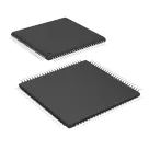
MIPS MCU, 120MHz, 1MB Flash, 256KB RAM, 2.3-3.6V, USB, TQFP-100 #Microcontroller
#commonpartslibrary
Properties
Microcontroller
Microchip
PIC32MK1024GPE100-I/PT
U
Pricing & Availability
DPN | Stock | Qty 1 |
|---|---|---|
2 | 0 | $9.213 |
1 | 0 | $0.00 |
1 | 3 | $19.8138 |
1 | 560 | $10.44 |
2 | 76–110 | $16.1212–$19.8829 |
Controls
Welcome 👋
Flux accelerates your PCB design with AI.
Create your account to start using this component and bring your ideas to life.
uet
copilot
Table