Chat
Welcome to Flux
Treat Flux like your intern. Tell it what you'd like to build and it'll get to work. You can also ask it questions, brainstorm ideas, and teach it your preferences. Learn More
Explain this part
Write a part description
Describe each pin
Operating conditions
Electrical max ratings
Part Specifications
Application circuits
Verify Part Details
Recommend similar parts
Check availability & lifecycle
how do I use Flux?

680 OHM
2y
@copilot how do I use Flux?
2y
Flux is a browser-based electronics CAD program designed to help you build electrical schematics and layout PCBs. Here's a basic walkthrough on how to get started:
-
Creating a project: Log in to your Flux account and click on "New Project". Here you can name your project and set other project options. If you don't have a Flux account yet, you can sign up and choose from one of the free plans.
-
Designing a Schematic: Next, navigate to the Schematic Editor. Here, you can drag and drop components from the component library onto the canvas to create your circuit.
-
Connecting the Components: Connect your components by drawing wires between the corresponding pins. Make sure to reference designators and pin names for accurate connections.
-
Creating a PCB Layout: Once your schematic is complete, switch over to the PCB layout designer. Flux will auto-generate a PCB layout based on your schematic. You can then move and rotate the components as desired and reroute the traces if needed.
-
Checking Your Work: Use Flux's 'Design Rule Check' (DRC) feature to ensure your PCB abides by all rules set and has no electrical or design issues.
-
Exporting Your Design: Once you're happy with your PCB layout, you can export your design files for manufacturing. Flux supports Gerber, Drill file and 3D model exports.
In case of more specific questions or troubleshooting needs, Flux provides various support channels such as their Slack community, issue-tracking tool for bug reports, feature request sections, contact page, and a rich library of video tutorials, crash courses, and recorded events[1]. Happy designing!
2y
Someone is typing...
3
how do I use Flux?
@copilot how do I use Flux?
2y
Flux is an electronic design automation tool that allows you to design electrical schematics and lay out Printed Circuit Boards (PCBs). Here is a basic step-by-step guide on how to use Flux:
-
Create an Account: If you haven't yet done so, create a Flux account.
-
Start a New Project: Once you're logged in, you can start a new project. Give the project a name and a brief description.
-
Design the Schematic: You can select components from Flux's library and drag them onto the canvas to create your schematic. Each component may be rotated, moved, or deleted as needed. You may also connect components using wires.
-
Layout the PCB: After designing the schematic, you can move on to the PCB layout. This is where you decide where each component and trace will be located on the actual physical board.
-
Design Review & Export: Check your design for any potential issues using Flux's design rule check (DRC). Afterwards, you can export your design as Gerber files, which are used for PCB manufacturing.
-
Ask for help when necessary: Should you encounter issues or require further assistance, Flux offers various support channels, including a Slack community, their issue-tracking tool, and a feature request section[1].
For more detailed tutorials and examples, you may want to check out Flux's YouTube channel [2].
Remember, patience and practice are key to becoming proficient with any new tool. Happy designing with Flux!
2y
Someone is typing...
3
explain this project.
alimentation 12v
2y
@copilot explain this project.
2y
Sure, this project revolves around a microcontroller which is a PIC16F628A-I/P from Microchip Technology. This is an 8-bit microcontroller that features 3.5KB of FLASH memory and operates at 20MHz.
The microcontroller is specified in a 18-PDIP package format. Each pin on this chip has potential different functions, which can be configured depending on the application requirement. Here are some details about the individual pins:
- RB6/T1OSC0/T1CKI/PGC (Pin 12): This pin is a bidirectional I/O pin and can also be used as Clock input for Timer 1 or for programming the device.
- Vref/AN2/RA2 (Pin 1): This pin can serve as a reference voltage or an Analog input (Channel 2)
- RB5 (Pin 11): This is a general purpose bidirectional I/O pin
- TOCKI/CMP2/RA4 (Pin 3): This pin can be used as an external clock input or comparator(CMP2) input.
- CMP1/AN3/RA3 (Pin 2): This pin can be used as an analog input or for comparing voltages.
MCLR/Vpp/RA5 (Pin 4): This input pin is used for device reset.- VDD (Pin 14): This pin is for power input(Battery or DC power source).
- RB4/PGM (Pin 10): This is a general purpose bidirectional I/O pin and can be used for programming the device.
- RB0/INT (Pin 6): This general purpose bidirectional I/O pin can be used for external interrupts.
- AN0/RA0 (Pin 17): This pin can be used as an analog input.
- RB7/T1OSI/PGD (Pin 13): This pin can function as a general purpose I/O and for programming the device.
- RB2/TX/CK (Pin 8): This general purpose I/O pin can be used for serial transmission.
- RB3/CCP1 (Pin 9): This pin can be used for Capture/Compare/PWM module.
- VSS (Pin 5): This is the ground pin for the microcontroller.
- AN1/RA1 (Pin 18): This pin can function as an analog input.
- CLKIN/OSC1/RA7 (Pin 16): This pin can be used to provide external clock and oscillator input.
- RB1/RX/DT (Pin 7): This pin can act as a receive line in serial communication.
- CLKOUT/OSC2/RA6 (Pin 15): This pin can be used for clock output or to provide an external oscillator.
No electrical connections have been made in this project yet, it's in an initial stage and no external components are added. Each pin's function can be customized based on your design's requirements. So far, it's just a microcontroller and its pins are not connected to anything.
2y
Someone is typing...
2
RB6/T1OSC0/T1CKI/PGC
Vref/AN2/RA2
RB5
TOCKI/CMP2/RA4
CMP1/AN3/RA3
~MCLR~/Vpp/RA5
VDD
RB4/PGM
RB0/INT
AN0/RA0
RB7/T1OSI/PGD
RB2/TX/CK
RB3/CCP1
VSS
AN1/RA1
CLKIN/OSC1/RA7
RB1/RX/DT
CLKOUT/OSC2/RA6
Reviews
 A generic fixed inductor suitable for rapid circuit topology development. The footprint automatically adapts based on the selected package, supporting standard SMD sizes (e.g., 0402, 0603, 0805) as well as well-known inductor packages such as SDR1806, PA4320, SRN6028, and SRR1260. Standard inductor values: 1.0 nH, 10 nH, 100 nH, 1.0 µH, 10 µH, 100 µH, 1.0 mH 1.2 nH, 12 nH, 120 nH, 1.2 µH, 12 µH, 120 µH, 1.2 mH 1.5 nH, 15 nH, 150 nH, 1.5 µH, 15 µH, 150 µH, 1.5 mH 1.8 nH, 18 nH, 180 nH, 1.8 µH, 18 µH, 180 µH, 1.8 mH 2.2 nH, 22 nH, 220 nH, 2.2 µH, 22 µH, 220 µH, 2.2 mH 2.7 nH, 27 nH, 270 nH, 2.7 µH, 27 µH, 270 µH, 2.7 mH 3.3 nH, 33 nH, 330 nH, 3.3 µH, 33 µH, 330 µH, 3.3 mH 3.9 nH, 39 nH, 390 nH, 3.9 µH, 39 µH, 390 µH, 3.9 mH 4.7 nH, 47 nH, 470 nH, 4.7 µH, 47 µH, 470 µH, 4.7 mH 5.6 nH, 56 nH, 560 nH, 5.6 µH, 56 µH, 560 µH, 5.6 mH 6.8 nH, 68 nH, 680 nH, 6.8 µH, 68 µH, 680 µH, 6.8 mH 8.2 nH, 82 nH, 820 nH, 8.2 µH, 82 µH, 820 µH, 8.2 mH #generics #CommonPartsLibraryjharwinbarrozo16.6k
- A generic fixed capacitor ideal for rapid circuit topology development. You can choose between polarized and non-polarized types, its symbol and the footprint will automatically adapt based on your selection. Supported options include standard SMD sizes for ceramic capacitors (e.g., 0402, 0603, 0805), SMD sizes for aluminum electrolytic capacitors, and through-hole footprints for polarized capacitors. Save precious design time by seamlessly add more information to this part (value, footprint, etc.) as it becomes available. Standard capacitor values: 1.0pF, 10pF, 100pF, 1000pF, 0.01uF, 0.1uF, 1.0uF, 10uF, 100uF, 1000uF, 10000uF 1.1pF, 11pF, 110pF, 1100pF 1.2pF, 12pF, 120pF, 1200pF 1.3pF, 13pF, 130pF, 1300pF 1.5pF, 15pF, 150pF, 1500pF, 0.015uF, 0.15uF, 1.5uF, 15uF, 150uF, 1500uF 1.6pF, 16pF, 160pF, 1600pF 1.8pF, 18pF, 180pF, 1800pF 2.0pF, 20pF, 200pF, 2000pF 2.2pF, 22pF, 220pF, 2200pF, 0.022uF, 0.22uF, 2.2uF, 22uF, 220uF, 2200uF 2.4pF, 24pF, 240pF, 2400pF 2.7pF, 27pF, 270pF, 2700pF 3.0pF, 30pF, 300pF, 3000pF 3.3pF, 33pF, 330pF, 3300pF, 0.033uF, 0.33uF, 3.3uF, 33uF, 330uF, 3300uF 3.6pF, 36pF, 360pF, 3600pF 3.9pF, 39pF, 390pF, 3900pF 4.3pF, 43pF, 430pF, 4300pF 4.7pF, 47pF, 470pF, 4700pF, 0.047uF, 0.47uF, 4.7uF, 47uF, 470uF, 4700uF 5.1pF, 51pF, 510pF, 5100pF 5.6pF, 56pF, 560pF, 5600pF 6.2pF, 62pF, 620pF, 6200pF 6.8pF, 68pF, 680pF, 6800pF, 0.068uF, 0.68uF, 6.8uF, 68uF, 680uF, 6800uF 7.5pF, 75pF, 750pF, 7500pF 8.2pF, 82pF, 820pF, 8200pF 9.1pF, 91pF, 910pF, 9100pF #generics #CommonPartsLibraryjharwinbarrozo1.5M
- A generic fixed resistor ideal for rapid circuit topology development. Its footprint automatically adapts based on the selected package case code—supporting 0402, 0603, 0805, 1203, and many other standard SMD packages, as well as axial horizontal and vertical configurations. Save precious design time by seamlessly add more information to this part (value, footprint, etc.) as it becomes available. Standard resistor values: 1.0 ohm, 10 ohm, 100 ohm, 1.0k ohm, 10k ohm, 100k ohm, 1.0M ohm 1.1 ohm, 11 ohm, 110 ohm, 1.1k ohm, 11k ohm, 110k ohm, 1.1M ohm 1.2 ohm, 12 ohm, 120 ohm, 1.2k ohm, 12k ohm, 120k ohm, 1.2M ohm 1.3 ohm, 13 ohm, 130 ohm, 1.3k ohm, 13k ohm, 130k ohm, 1.3M ohm 1.5 ohm, 15 ohm, 150 ohm, 1.5k ohm, 15k ohm, 150k ohm, 1.5M ohm 1.6 ohm, 16 ohm, 160 ohm, 1.6k ohm, 16k ohm, 160k ohm, 1.6M ohm 1.8 ohm, 18 ohm, 180 ohm, 1.8K ohm, 18k ohm, 180k ohm, 1.8M ohm 2.0 ohm, 20 ohm, 200 ohm, 2.0k ohm, 20k ohm, 200k ohm, 2.0M ohm 2.2 ohm, 22 ohm, 220 ohm, 2.2k ohm, 22k ohm, 220k ohm, 2.2M ohm 2.4 ohm, 24 ohm, 240 ohm, 2.4k ohm, 24k ohm, 240k ohm, 2.4M ohm 2.7 ohm, 27 ohm, 270 ohm, 2.7k ohm, 27k ohm, 270k ohm, 2.7M ohm 3.0 ohm, 30 ohm, 300 ohm, 3.0K ohm, 30K ohm, 300K ohm, 3.0M ohm 3.3 ohm, 33 ohm, 330 ohm, 3.3k ohm, 33k ohm, 330k ohm, 3.3M ohm 3.6 ohm, 36 ohm, 360 ohm, 3.6k ohm, 36k ohm, 360k ohm, 3.6M ohm 3.9 ohm, 39 ohm, 390 ohm, 3.9k ohm, 39k ohm, 390k ohm, 3.9M ohm 4.3 ohm, 43 ohm, 430 ohm, 4.3k ohm, 43K ohm, 430K ohm, 4.3M ohm 4.7 ohm, 47 ohm, 470 ohm, 4.7k ohm, 47k ohm, 470k ohm, 4.7M ohm 5.1 ohm, 51 ohm, 510 ohm, 5.1k ohm, 51k ohm, 510k ohm, 5.1M ohm 5.6 ohm, 56 ohm, 560 ohm, 5.6k ohm, 56k ohm, 560k ohm, 5.6M ohm 6.2 ohm, 62 ohm, 620 ohm, 6.2k ohm, 62K ohm, 620K ohm, 6.2M ohm 6.8 ohm, 68 ohm, 680 ohm, 6.8k ohm, 68k ohm, 680k ohm, 6.8M ohm 7.5 ohm, 75 ohm, 750 ohm, 7.5k ohm, 75k ohm, 750k ohm, 7.5M ohm 8.2 ohm, 82 ohm, 820 ohm, 8.2k ohm, 82k ohm, 820k ohm, 8.2M ohm 9.1 ohm, 91 ohm, 910 ohm, 9.1k ohm, 91k ohm, 910k ohm, 9.1M ohm #generics #CommonPartsLibraryjharwinbarrozo1.5M
- An electrical connector acting as reusable interface to a conductor and creating a point where external circuits can be connected.Terminal
- Wirelessly connects nets on schematic. Used to organize schematics and separate functional blocks. To wirelessly connect net portals, give them same designator. #portaljharwinbarrozo43.0M
- General Purpose Thick Film Standard Power and High-Power Chip Resistor 47 kOhms ±5% 0.125W, 1/8W Chip Resistor 0805 (2012 Metric) Automotive AEC-Q200 Thick Film Features: - RMCF – standard power ratings - RMCP – high power ratings - Nickel barrier terminations standard - Power derating from 100% at 70ºC to zero at +155ºC - RoHS compliant, REACH compliant, and halogen free - AEC-Q200 compliantjharwinbarrozo1.2M
- 10 µF 16 V Aluminum - Polymer Capacitors Radial, Can - SMD 30mOhm 2000 Hrs @ 105°C #commonpartslibrary #capacitor #aluminumpolymer #radialcanjharwinbarrozo1.2M
- Battery Holder (Open) Coin, 20.0mm 1 Cell SMD (SMT) Tab bate or batt #forLedBlinkjharwinbarrozo700.5k


PIC16F628A-I/P
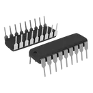
PIC series Microcontroller IC 8-Bit 20MHz 3.5KB (2K x 14) FLASH 18-PDIP
#Microcontroller #PIC16
#commonpartslibrary
Properties
Pricing & Availability
DPN | Stock | Qty 1 |
|---|---|---|
4 | 0–220 | $2.875–$2.9097 |
1 | 0 | $0.00 |
1 | 180 | $3.7477 |
1 | 2K | $2.94 |
1 | 25 | $3.20 |
13 | 56–1.5K | $2.64–$4.3566 |
Controls
Welcome 👋
Flux accelerates your PCB design with AI.
Create your account to start using this component and bring your ideas to life.
mohamedaminechen
copilot
Table