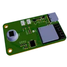
电路工作原理解析

最多加2个器件:磁珠 + 磁珠后新增1颗就地去耦电容,形成3V3_A支路只供模拟前端。
你的目标是:最多新增 2 个器件(磁珠 + 磁珠后1颗就地去耦电容),生成独立 3V3_A 支路,并且 只给模拟前端PIR1 + U3)供电。
计划已更新并且 ready_to_execute。执行内容包括:
  1. 原理图上把 PIR1U3 的供电脚从 3V3 迁到新网标 3V3_A,确认没有其他器件误接入。
  2. 新增 1 颗磁珠(3V3 -> 3V3_A)+ 1 颗磁珠后的就地去耦电容(3V3_A -> GND)。
  3. PCB侧让“磁珠 -> 电容 -> 模拟负载”的环路最短,并隔离远离 J1 / LED1 / U1 的噪声区域。
  4. 跑 ERC/DRC 验证。
请在计划栏点击 Start 开始执行;需要我偏好磁珠封装(0603/0805)或电容封装(0402/0603)也可以再告诉我。
修改PCB,实现抗干扰的效果
你的目标是:直接修改PCB(并同步必要的原理图连线),通过新增2个器件建立3V3_A模拟支路(磁珠 + 磁珠后就地去耦),只给模拟前端供电,从而降低地噪声、3.3 V纹波与数字开关噪声对PIR1/U3的干扰。
我已生成并更新可执行计划(ready_to_execute)。请在计划栏点击Start开始执行。完成后会确保仅PIR1U3接到3V3_A,并通过DRC/ERC验证。
查模拟前端供电
查板上布局噪声源距离
直接跑DRC/ERC
找磁珠和电容

To get started, talk to Flux or create a New Document.

Documents

    Documents are markdown text files which describe project goals, capture details, or even simulation outputs.

    Assets

    Motion Detector Reference Design.png

    Motion Detector Reference Design.png

    Motion Detector Reference DesignThumbnail

    Motion Detector Reference Design

    Motion Detector Reference Design thumbnail
    This is a motion detector circuit using an ESP32 microcontroller and PIR sensor. It features USB-C connectivity, RGB LED indication, push buttons and is powered by a 3.3V supply. #referenceDesign #edge-computing #edgeComputing #espressif #template #iot #PIR #esp32 #reference-design

    Pricing & Availability

    Distributor

    Qty 1

    Digi-Key

    $3.75–$5.06

    LCSC

    $8.18

    Mouser

    $7.98

    Controls