Project Overview and Design Analysis
Thought for 1 min 14 sec
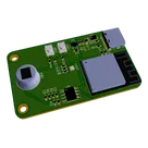
The “Motion Detector Module” is designed for IoT and edge‑computing applications where a compact, low‑power sensor can detect motion and communicate the event wirelessly. Here’s a breakdown of its design and functionality:
-
Purpose and Overall Functionality
- Motion Sensing: At its core, a PIR sensor (IRA‑S230ST01) detects infrared changes when motion occurs.
- Processing and Connectivity: An ESP32‑S3‑MINI module (ESP32‑S3‑MINI‑1‑N8) acts as the central processor, enabling both WiFi and Bluetooth/BLE communications for transmitting motion events or receiving remote commands.
- User Interaction: The module includes tactile switches (such as PTS815) for manual input and an RGB LED (LTST‑C19HE1WT) for visual status—indicating whether motion is detected or transmitting error/status signals.
- USB-C Connectivity: A USB‑C connector (TYPE‑C‑31‑M‑12) provides an interface for programming, power, or even data exchange.
-
Core Components and Their Interactions
- The PIR sensor sends a signal upon detecting motion to one of the ESP32’s input pins.
- The ESP32 microcontroller processes the sensor data and may (for example) update the RGB LED status or send notifications over WiFi/Bluetooth.
- The voltage regulator (AP2112K‑3.3TRG1) provides a stable 3.3 V supply that powers the ESP32, sensor, and other peripheral circuits.
- Passive components (resistors and capacitors) are distributed around power pins and signal lines to ensure proper decoupling, reduce noise, and maintain circuit stability.
- Net portals and ground components are used extensively to ensure that signal, power, and ground paths are clearly defined and interconnected throughout the schematic.
-
Design, Implementation, and Functionality Step by Step
- Sensor Integration: The PIR sensor is connected to the microcontroller’s input, allowing it to monitor ambient infrared levels.
- Microcontroller Setup: The ESP32‑S3 is chosen for its integrated WiFi and Bluetooth capability, supporting remote communication and over‑the‑air updates.
- Power Management: With a supply rail set at 3.3 V, the design uses an efficient LDO (AP2112K‑3.3TRG1) combined with proper decoupling capacitors on both the input and output to ensure stable operation.
- User Interface: Tactile switches are front‑faced for manual intervention (for example, to reset or change operating modes), and the RGB LED offers immediate visual feedback based on system status.
- Connectivity: The USB‑C port simplifies programming and debugging while also offering potential power delivery and data exchange, adding flexibility to the module.
-
Key Technologies, Trade‑offs, and Design Choices
- ESP32‑S3: Chosen for its rich set of features and low‑power operation. Trade‑offs include managing higher integration compared to simpler MCUs.
- PIR Sensor: A mature technology for motion detection; its placement and tuning can affect sensitivity and false triggering.
- Voltage Regulation: A regulator-based design (rather than a switching converter) was likely selected for its simplicity and low noise characteristics despite a potential trade‑off in efficiency.
- Component Selection: Use of surface‑mount parts (0603 and 0805 packages) supports a compact design ideal for integration into consumer or industrial IoT devices.
-
Potential Challenges and Performance Considerations
- Noise and Decoupling: Ensuring adequate filtering around the microcontroller and sensor is critical, as digital switching can cause interference in sensitive analog sensor readings.
- Thermal and Power Considerations: Operating from a 3.3 V rail at low power is ideal for battery‑powered or always‑on IoT devices, but it requires tight control over power supply noise and voltage stability.
- Sensor Calibration: Adjusting the PIR sensor’s sensitivity and field‑of‑view may require fine‑tuning based on the target environment.
-
Real‑world Applications and Future Enhancements
- Applications: The module can be used in security systems, smart lighting, or as part of a home automation network where motion detection triggers actions (like turning on lights or sending notifications).
- Improvements and Scalability: Future enhancements might include incorporating sensor fusion techniques, adaptive power management, or integration with cloud platforms for real‑time monitoring. There may also be opportunities to refine component layout for better thermal performance and reduced electromagnetic interference.
Overall, the design balances functionality with a compact footprint and efficient connectivity. Each choice—from the microcontroller to the passive elements—reflects an optimization for low‑power IoT sensing with robust communication capabilities.