Recommendation:
The Waveshare RP2350-USB-A is a right-angle USB-A female receptacle. Of the above, U231-091N-3GRC10-5 most closely matches (3 A rating, right-angle Type-A female).
Let me know if you’d like to add that one (or another) to your schematic!
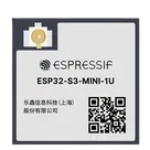
To create an adapter from the USR−C210 to the ESP32−S3−MINI−1U−N8, you'll need to establish connections between the pins of these two modules for the desired communication interface. The USR-C210 is a serial device server, so we can leverage a UART interface for communication with the ESP32-S3.
Assumptions:
You want to connect these modules using a UART interface.
We'll use one of the available UART ports on the ESP32-S3-MINI-1U.
We'll assume the USR-C210 is powered separately, or you have a power arrangement that handles both devices.
Connections:
Power Connections:
Make sure both devices are powered appropriately. The ESP32-S3-MINI-1U module requires a 3.3V supply, so connect it to a 3.3V source if not already provided.
UART Connections:
Connect the USR-C210's TX (Transmit) pin to the ESP32-S3-MINI-1U's RX pin.
Connect the USR-C210's RX (Receive) pin to the ESP32-S3-MINI-1U's TX pin.
Here's a specific connection example using the ESP32-S3's default UART pins:
Connect USR-C210:TX to ESP32-S3:RXD0.
Connect USR-C210:RX to ESP32-S3:TXD0.
Ground Connection:
Ensure both devices share a common ground: Connect one of the GND pins of the USR-C210 to one of the GND pins on the ESP32-S3-MINI-1U.
UART Configuration:
Configure the UART settings on the ESP32 to match those required by the USR-C210, typically 9600 or 115200 baud, 8 data bits, no parity, and 1 stop bit (8N1).
Considerations:
Make sure the logic levels of both devices match. If the USR-C210 is working at a different logic level, a level shifter might be necessary.
Ensure proper signal integrity, especially if the connection is over a long distance.
If you have specific pin preferences or additional components to integrate, let me know, and we can adjust the setup accordingly!
1y
Someone is typing...
4
Add usb C connector and do the connection for usb on s3
To connect a USB-C connector to the ESP32-S3-MINI-1U-N8, you will typically want to create connections that enable USB communication, which usually involves connecting USB data lines as well as providing power to the device.
Components Required
USB-C Connector:
Pins typically include VBUS, GND, D+, D-, and configuration pins for orientation detection.
Resistors and Capacitors:
CC resistors (typically around 5.1kΩ) for configuring the orientation of the connector.
Decoupling capacitors for power filtering.
Connections
For the ESP32-S3, you primarily need to connect the USB data lines and power lines. Based on your design, here are the typical connections:
VCC (3.3V) Power Supply:
Connect USB-C:VBUS to your system's power supply or 3V3, through a voltage regulator if necessary, to provide power to the ESP32.
Ground:
Connect USB-C:GND to GND (any ground pin).
USB Data Lines:
Connect USB-C:D+ to IO9 (or the appropriate USB data pin on your ESP32-S3).
Connect USB-C:D- to IO8 (or the appropriate USB data pin on your ESP32-S3).
USB Configuration Channel (CC):
Connect the CC1 and CC2 pins of the USB-C connector through a 5.1kΩ resistor to ground. This resistor helps in determining the cable orientation and power role.
Additional Notes
Make sure the power supply can handle the maximum current that your ESP32 will draw.
Add decoupling capacitors close to the VCC pins on the ESP32-S3 to stabilize the voltage supply.
Would you like help selecting specific components, or do you have any additional requirements for this connection?
To add a USB-C port to your ESP32-S3-MINI-1U-N8 project and map it correctly, you need a USB-C connector and a USB-to-UART bridge (such as the CP2102N or CH340). This setup will allow you to program the ESP32 through USB and communicate via UART. Here's a step-by-step guide on how to make the connections:
picknicker
copilot
- You want to connect these modules using a UART interface.
- We'll use one of the available UART ports on the ESP32-S3-MINI-1U.
- We'll assume the USR-C210 is powered separately, or you have a power arrangement that handles both devices.
Connections:- Ground Connection:
- Ensure both devices share a common ground: Connect one of the GND pins of the USR-C210 to one of the GND pins on the ESP32-S3-MINI-1U.
UART Configuration:- Configure the UART settings on the ESP32 to match those required by the USR-C210, typically 9600 or 115200 baud, 8 data bits, no parity, and 1 stop bit (8N1).
Considerations: