Desain PCB dengan ESP32
0:00
Work done
- Updated project description to a clear, concise statement of goals
Tasks remaining
-
Project goals and architecture
- Generate and save the mermaid system architecture diagram in the “System Architecture” project property
- Add project properties “BatteryCapacity” = "500 mAh" and “ButtonType” = "SMD"
-
Key components
- Add ESP32-C3-MINI-1, TP4056, USB-C connector, JST-PH battery connector, 3.3 V regulator
- Add OLED I2C module, five push-button switches, programming UART pads
-
Supporting components and power
- Place and configure 100 nF decoupling caps and 10 µF bulk cap
- Add 4.7 kΩ pull-ups for I2C and buttons
- Add USB-C TVS diode and CC resistors for input protection
-
Connectivity
- Wire power nets: USB-C → TP4056 VIN → TP4056 BAT → LiPo connector and 3.3 V regulator
- Wire regulator output to ESP32 VCC, OLED VCC, and decoupling
- Wire I2C nets with pull-ups
- Wire five buttons with pull-ups to ESP32 GPIOs, EN and RST lines with reset button
- Wire UART pads to ESP32 TX/RX
-
Schematic review
- Perform ERC, label nets, and add test points
-
Final recommendations
- Add design note recommending 500–1000 mAh LiPo and ~0.5 C charge current with 25% margin
Success criteria
- Not yet met: schematic components, power subsystem, interfaces, and design notes still need to be added and verified.
Next step
Generate the mermaid system architecture diagram and save it to the “System Architecture” property.
92 days
Ready.
are there any issues in this project?
@copilot are there any issues in this project?
1y
Someone is typing...
8
create a high level mermaid block diagram of this project. Include key component...
Add charging modules for a total of 6 batteries with 2 amp charge
1y
@copilot create a high level mermaid block diagram of this project. Include key component's manufacturer part number in each block whenever possible.
1y
Sure! Below is a high-level Mermaid block diagram for your TP4056 Li-ion single-cell charger project using the key components and their manufacturer part numbers.
graph TD;
    VIN[VIN - Power Input]
    BATTERY[Battery]
    U1(TP4056 - NanJing Top Power ASIC Corp.)

    C1["C1 - Capacitor\n10uF"]
    C2["C2 - Capacitor\n0.1uF"]
    C3["C3 - Capacitor\n10uF"]
    Rprog["Rprog - Resistor\n1.2k"]
    R1["R1 - Resistor\n1k"]
    R2["R2 - Resistor\n1k"]

    VIN --> U1
    U1 -->|VCC| C1
    U1 -->|VCC| C2
    U1 -->|BAT| C3
    U1 -->|PROG| Rprog
    Rprog --> GND((GND))

    U1 -->|TEMP| TEMP_PIN["TEMP Pin"]
    U1 -->|~CHRG| R1
    R1 --> LED1["CHRG LED"]

    U1 -->|~STDBY| R2
    R2 --> LED2["STDB LED"]

    U1 -->|BAT| BATTERY

    GND --> C1
    GND --> C2
    GND --> C3
    GND --> U1
- VIN: Power input terminal.
- BATTERY: Power output to the battery.
- U1: TP4056 charging IC from NanJing Top Power ASIC Corp.
- C1, C2, C3: Capacitors.
- Rprog: Programming resistor to set the output current.
- R1, R2: Current limiting resistors for indicator LEDs.
- TEMP_PIN: TEMP pin connection for the TP4056.
- LED1, LED2: Charge status LEDs (CHRG and STDB).
This diagram provides a high-level overview of the connections between the key components of your TP4056 charging circuit.
1y
Someone is typing...
3
create a high level mermaid block diagram of Rprog value. Include key component'...
@copilot create a high level mermaid block diagram of Rprog value. Include key component's manufacturer part number in each block whenever possible.
1y
Sure! Let's create a high-level Mermaid block diagram for the TP4056 module highlighting the Rprog value and key components.
Here's the Mermaid code for the block diagram:
Diagram
You can paste this code into a Mermaid live editor or a tool that supports Mermaid syntax to visualize it. Let me know if there's anything specific you want to adjust or if you need further assistance!
1y
Someone is typing...
5
create a high level mermaid block diagram of this project. Include key component...
1y
Here's a high-level mermaid block diagram of the TP4056 Li-ion single cell charger project. This diagram highlights the key components, their connections, and includes the manufacturer part number for the TP4056 IC.
graph TD;
    VIN["VIN\nPower Input"] -->|VCC| U1[TP4056\nU1: NanJing Top Power ASIC Corp.];
    U1 -->|BAT| VBAT["VBAT\nBattery Output"];
    U1 -->|GND| GND["GND\nGround"];
    U1 -->|PROG| Rprog["Rprog\n1.2k Ohm"];
    U1 --> |~CHRG| R1["R1\n1k Ohm"];
    U1 --> |~STDBY| R2["R2\n1k Ohm"];
    CHRG["CHRG\nLED"] -->|A| U1;
    STDB["STDB\nLED"] -->|K| U1;
    C1["C1\n10uF"] -->|VCC| U1;
    C2["C2\n0.1uF"] -->|VCC| U1;
    C3["C3\n10uF"] -->|BAT| VBAT;
    TEMP["TEMP\nPin"] --> U1;
    GND -->|Ground Nodes| C1 & C2 & C3 & Rprog;
This diagram summarizes the core components and their connections based on the provided project details. Let me know if there's anything you'd like to adjust or add!
1y
Someone is typing...
6
Kann ich das so für einen ESP32 als Lipo Lade Manager und Batterymanager brauche...
1y
Ja, du kannst den TP4056 Modul als LiPo Lade- und Batteriemanager für einen ESP32 nutzen, solange es sich um eine 1S LiPo-Batterie handelt. Der TP4056 ist dafür ausgelegt, ein einzelnes LiPo-Element zu laden. Beachte einige wichtige Punkte, um sicherzustellen, dass das Setup mit dem ESP32 korrekt funktioniert:
-
Ladestrom: Der eingestellte Ladestrom von 900mA ist für viele 1S LiPo-Batterien geeignet, aber stelle sicher, dass dieser für Deine Batterie sicher ist. Normale LiPo-Batterien sollten mit einem Ladestrom von 0.5C bis 1C geladen werden, basierend auf der Kapazität der Batterie.
-
ESP32 Versorgung: Stelle sicher, dass die ESP32 Versorgungsspannung nach der Batterie über einen Spannungsregler auf 3,3V reduziert wird, da die Batterie eine höhere Spannung als die benötigten 3,3V ausgeben kann.
-
Verbindungen zum TP4056:
- Verbindung zum ESP32 hängt von spezifischen Funktionen ab, die du implementieren willst:
- Du kannst die CHRG- und STDB-Signale des TP4056 für Ladezustandsanzeigen nutzen.
- Schließe die Batterieausgänge des TP4056 an den Spannungsregler, bevor sie den ESP32 versorgen.
- Verbindung zum ESP32 hängt von spezifischen Funktionen ab, die du implementieren willst:
-
Schutzschaltung: Implementiere möglicherweise Schutzschaltungen, wie Überspannungs- und Tiefenentladeschutz, da der TP4056 selbst dies nicht bietet.
Hier sind einige grundlegende Anschlüsse:
- Verbindung der Batterie:
- Verbinde den BAT+ Anschluss des TP4056 mit dem Pluspol der Batterie.
- Verbinde den BAT- Anschluss des TP4056 mit dem Minuspol der Batterie.
- Verbindung zu VIN und GND:
- Verbinde einen USB oder anderen geeigneten Stromquelle an VIN und GND des TP4056.
Falls du weitere Informationen oder Unterstützung benötigst, lass es mich wissen!
1y
Someone is typing...
7
GND
VIN
C2
Capacitance
0.1u F
VIN
CHRG
R1
Resistance
1k Ω
VIN
C1
Capacitance
10u F
R2
Resistance
1k Ω
VIN
STDB
VIN
Reviews

- Wirelessly connects nets on schematic. Used to organize schematics and separate functional blocks. To wirelessly connect net portals, give them same designator. #portaljharwinbarrozo43.0M
- Wirelessly connects power nets on schematic. Identical to the net portal, but with a power symbol. Used to organize schematics and separate functional blocks. To wirelessly connect power net portals, give them the same designator. #portal #powerjharwinbarrozo11.4M
- A generic fixed resistor for rapid developing circuit topology. Save precious design time by seamlessly add more information to this part (value, footprint, etc.) as it becomes available. Standard resistor values: 1.0Ω 10Ω 100Ω 1.0kΩ 10kΩ 100kΩ 1.0MΩ 1.1Ω 11Ω 110Ω 1.1kΩ 11kΩ 110kΩ 1.1MΩ 1.2Ω 12Ω 120Ω 1.2kΩ 12kΩ 120kΩ 1.2MΩ 1.3Ω 13Ω 130Ω 1.3kΩ 13kΩ 130kΩ 1.3MΩ 1.5Ω 15Ω 150Ω 1.5kΩ 15kΩ 150kΩ 1.5MΩ 1.6Ω 16Ω 160Ω 1.6kΩ 16kΩ 160kΩ 1.6MΩ 1.8Ω 18Ω 180Ω 1.8KΩ 18kΩ 180kΩ 1.8MΩ 2.0Ω 20Ω 200Ω 2.0kΩ 20kΩ 200kΩ 2.0MΩ 2.2Ω 22Ω 220Ω 2.2kΩ 22kΩ 220kΩ 2.2MΩ 2.4Ω 24Ω 240Ω 2.4kΩ 24kΩ 240kΩ 2.4MΩ 2.7Ω 27Ω 270Ω 2.7kΩ 27kΩ 270kΩ 2.7MΩ 3.0Ω 30Ω 300Ω 3.0KΩ 30KΩ 300KΩ 3.0MΩ 3.3Ω 33Ω 330Ω 3.3kΩ 33kΩ 330kΩ 3.3MΩ 3.6Ω 36Ω 360Ω 3.6kΩ 36kΩ 360kΩ 3.6MΩ 3.9Ω 39Ω 390Ω 3.9kΩ 39kΩ 390kΩ 3.9MΩ 4.3Ω 43Ω 430Ω 4.3kΩ 43KΩ 430KΩ 4.3MΩ 4.7Ω 47Ω 470Ω 4.7kΩ 47kΩ 470kΩ 4.7MΩ 5.1Ω 51Ω 510Ω 5.1kΩ 51kΩ 510kΩ 5.1MΩ 5.6Ω 56Ω 560Ω 5.6kΩ 56kΩ 560kΩ 5.6MΩ 6.2Ω 62Ω 620Ω 6.2kΩ 62KΩ 620KΩ 6.2MΩ 6.8Ω 68Ω 680Ω 6.8kΩ 68kΩ 680kΩ 6.8MΩ 7.5Ω 75Ω 750Ω 7.5kΩ 75kΩ 750kΩ 7.5MΩ 8.2Ω 82Ω 820Ω 8.2kΩ 82kΩ 820kΩ 8.2MΩ 9.1Ω 91Ω 910Ω 9.1kΩ 91kΩ 910kΩ 9.1MΩ #generics #CommonPartsLibraryjharwinbarrozo1.5M
- A generic fixed capacitor ideal for rapid circuit topology development. You can choose between polarized and non-polarized types, its symbol and the footprint will automatically adapt based on your selection. Supported options include standard SMD sizes for ceramic capacitors (e.g., 0402, 0603, 0805), SMD sizes for aluminum electrolytic capacitors, and through-hole footprints for polarized capacitors. Save precious design time by seamlessly add more information to this part (value, footprint, etc.) as it becomes available. Standard capacitor values: 1.0pF 10pF 100pF 1000pF 0.01uF 0.1uF 1.0uF 10uF 100uF 1000uF 10,000uF 1.1pF 11pF 110pF 1100pF 1.2pF 12pF 120pF 1200pF 1.3pF 13pF 130pF 1300pF 1.5pF 15pF 150pF 1500pF 0.015uF 0.15uF 1.5uF 15uF 150uF 1500uF 1.6pF 16pF 160pF 1600pF 1.8pF 18pF 180pF 1800pF 2.0pF 20pF 200pF 2000pF 2.2pF 22pF 20pF 2200pF 0.022uF 0.22uF 2.2uF 22uF 220uF 2200uF 2.4pF 24pF 240pF 2400pF 2.7pF 27pF 270pF 2700pF 3.0pF 30pF 300pF 3000pF 3.3pF 33pF 330pF 3300pF 0.033uF 0.33uF 3.3uF 33uF 330uF 3300uF 3.6pF 36pF 360pF 3600pF 3.9pF 39pF 390pF 3900pF 4.3pF 43pF 430pF 4300pF 4.7pF 47pF 470pF 4700pF 0.047uF 0.47uF 4.7uF 47uF 470uF 4700uF 5.1pF 51pF 510pF 5100pF 5.6pF 56pF 560pF 5600pF 6.2pF 62pF 620pF 6200pF 6.8pF 68pF 680pF 6800pF 0.068uF 0.68uF 6.8uF 68uF 680uF 6800uF 7.5pF 75pF 750pF 7500pF 8.2pF 82pF 820pF 8200pF 9.1pF 91pF 910pF 9100pF #generics #CommonPartsLibraryjharwinbarrozo1.5M
- A generic fixed inductor for rapid developing circuit topology. *You can now change the footprint and 3D model at the top level anytime you want. This is the power of #genericsjharwinbarrozo15.4k
- An electrical connector acting as reusable interface to a conductor and creating a point where external circuits can be connected.Terminal
- 47 kOhms ±5% 0.125W, 1/8W Chip Resistor 0805 (2012 Metric) Automotive AEC-Q200 Thick Film #forLedBlinkjharwinbarrozo1.2M
- 10uF Capacitor Aluminum Polymer 20% 16V SMD 5x5.3mm #forLedBlink #commonpartslibrary #capacitor #aluminumpolymer #radialcanjharwinbarrozo1.2M
- Yellow 595nm LED Indication - Discrete 1.7V 1206 (3216 Metric) #forLedBlinkjharwinbarrozo1.1M


Inspect
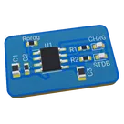
TP4056 Module
Controls
Properties
Connectivity
WiFi
Domain
Consumer Electronics
Power Requirements
USB
Human Interface
Display
System Architecture
```mermaid
flowchart TD
USB_C["USB-C Connector"] --> TP4056["TP4056 Charger"]
TP4056 --> LiPo["LiPo Battery Connector"]
TP4056 --> Reg3v3["3.3V Regulator"]
Reg3v3 --> ESP32["ESP32-C3-MINI-1"]
ESP32 --> I2C_OLED["I2C OLED Display"]
I2C_OLED --> PullUps["I2C Pull-up Resistors"]
ESP32 --> Buttons["Push Buttons\nUp, Down, Left, Right, Reset"]
ESP32 --> UART["Programming UART Pads"]
```
Availability & Pricing
| Distributor | Qty 1 | |
|---|---|---|
| LCSC | $0.07–$0.11 | |
Assets
- TP4056 Module-removebg-preview.png
id=TP4056 Module-removebg-preview
Thumbnail

Welcome 👋
Flux accelerates your PCB design with AI.
Create your account to start using this component and bring your ideas to life.
17kelvin
copilot
Rprogvalue is a resistance used to program a charging current in a battery charging circuit such as the one in this design that uses a TP4056 chip. The TP4056 is a standalone linear Li-Ion battery charger which allows for programmable charging current.Rprogvalue according to the equation specified in the TP4056 datasheet:PROGpin and Ground.Rprogis set to 1.2k Ohms, indicating a designed output current of 900mA. This means that the battery will be charged at 900mA until the charge is complete, at which point the charging current will significantly decrease.