GPIO Pin Mapping Header File

Generate a C/C++ pin mapping header file for the microcontroller in this design. Define named constants for each GPIO pin based on the schematic net names and connections. Include comments describing the function of each pin and the connected peripheral.
I can’t generate the header from the schematic right now because AI tool execution is unavailable due to no remaining ACUs, and I don’t have read access to inspect the project pins in this session.
What remains:
  • Inspect the schematic for the microcontroller part and its GPIO-to-net connections.
  • Create a C/C++ header file with named constants based on the actual schematic net names.
  • Add comments for each pin describing the connected peripheral/function.
If you can paste the MCU pin/net list here, I can draft the header directly from that text.
Paste pin list
Ask paste format
Show header example
Inspect GPIO nets
how do I use Flux?

@copilot how do I use Flux?
1y
To get started with Flux, you can follow these general steps:
  1. Create a Flux Account: Sign up for an account on Flux.ai.
  2. Migrate Projects: If you have existing projects in tools like EasyEDA or KiCad, you can follow the migration tutorials to bring them into Flux. Here are links to the tutorials for
    [1] and
    [2].
  3. Learn the Features: To get a comprehensive look at Flux’s features and how to integrate them into your workflow, check out the full documentation[3].
  4. Using the Simulator: To learn how to use the simulator within Flux, you can refer to the available tutorials[4].
  5. Hands-On Practice: Start by creating a new project and experimenting with the schematic and PCB layout tools. Add components from the library, connect them, and simulate your designs.
  6. Community and Resources: Engage with community resources, participate in discussions, and stay updated with Flux's news and updates.
Is there a specific aspect of using Flux you want to dive deeper into? Let me know!
1y
4
L1
Inductance
33uH
D1
VOUT
+5V
+12V
+12V
VIN
+5V
+5V
R2
Resistance
1kΩ
C2
Capacitance
100uF
ON/OFF
C3
Capacitance
470uF
U1
R1
Resistance
3.0kΩ
C1
Capacitance
1.2nF

To get started, talk to Flux or create a New Document.

Documents

    Documents are markdown text files which describe project goals, capture details, or even simulation outputs.

    Assets

    LM2596-removebg-preview.png

    LM2596-removebg-preview.png

    LM2596-removebg-preview
    LM2596 Buck converter 5V-removebg-preview.png

    LM2596 Buck converter 5V-removebg-preview.png

    LM2596 Buck converter 5V-removebg-previewThumbnail

    LM2596 Buck converter 5V

    LM2596 Buck converter 5V thumbnail
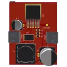
    This project is a DC-DC Buck converter based on the LM2596 IC. It is designed to step down the input voltage from 12V to a regulated output of 5V #Buck #LM2596 #project

    Properties

    Properties describe core aspects of the project.

    Pricing & Availability

    Distributor

    Qty 1

    Digi-Key

    $1.89–$3.76

    LCSC

    $2.96

    Mouser

    $3.70

    Controls