Power Consumption of U1
Thought for 40 sec
344 days
To answer precisely, we use the HC32L110B6YA datasheet specs for supply current and multiply by your VCC. From the datasheet for U1:
At VCC = 3.3 V, typical supply current (all peripherals off) is:
- Run in RAM, RCH clock:
- 4 MHz: IDD typ = 220 µA → P ≈ 0.73 mW
- 8 MHz: 400 µA → 1.32 mW
- 16 MHz: 740 µA → 2.44 mW
- 24 MHz: 1080 µA → 3.56 mW
- 32 MHz: 1400 µA → 4.62 mW
- Sleep mode (all peripherals off), RCH clock:
- 4 MHz: 110 µA → 0.36 mW
- 8 MHz: 190 µA → 0.63 mW
- 16 MHz: 330 µA → 1.09 mW
- 24 MHz: 470 µA → 1.55 mW
- 32 MHz: 580 µA → 1.91 mW
Notes from the datasheet:
- Currents depend on voltage, temperature, clock source/frequency, peripheral usage, I/O loading, code location, etc.
- The above “Run in RAM” figures are at VCC = 3.3 V, VCAP = 1.55 V, RCH clock, peripherals off.
- If running from Flash or enabling peripherals, currents are higher (datasheet provides additional tables).
If you tell me your intended clock frequency, supply voltage, and whether you’ll run from Flash or RAM (and which peripherals are enabled), I can quote the closest datasheet row and compute the corresponding power.
16 MHz Flash run
24 MHz RAM run
8 MHz Sleep mode
32 MHz Flash with ADC/SPI
@docbrown how much power does this component here consume?

@docdrown are you here?
3y

To provide the power consumption information for a component, I need to know the specific component in question. Please provide the designator or part name from the list of components you provided earlier, and I'll provide the information you're looking for.
3y
@natarius, I assume you're referring to the HC32L110B6YA microcontroller. Unfortunately, I don't have the exact power consumption numbers for this specific microcontroller, but it belongs to the HC32L110 series, which is known for its low power consumption. To find the exact numbers, consult the datasheet: https://www.hdsc.com.cn/cn/Index/downloadFile/modelid/65/id/8/key/0
Remember that power consumption can vary depending on the microcontroller's operating modes, clock frequency, peripherals used, and specific settings.
3y
Someone is typing...
7
1


10
@docbrown whats this component connected to?
My apologies for the confusion. For capacitor C3 (100nF non-polarized capacitor), the connections are as follows:
- Pin P1 of C3 is connected to SW1 (Net 2)
- Pin P2 of C3 is connected to Ground (Net 0)
In summary, C3 is connected between SW1 and Ground.
3y
Ah, I see you meant C3 now! Capacitor C3 is a 100nF non-polarized capacitor with the following connections:
- Pin P1 of C3 is connected to SW1 (Net 2)
- Pin P2 of C3 is connected to Ground (Net 0)
In summary, C3 is connected between SW1 and Ground.
3y
I meant C3
3y
I'm sorry, but you haven't specified which component you're referring to. Please provide the designator or part name of the component you want information about, and I'll gladly help you understand its connections.
3y
Someone is typing...
8
explain this project.

1y
Certainly! Let's break down the project:
Overview
This project involves creating a breakout board for the HC32L110B6YA-CSP16 microcontroller. A breakout board is a small PCB (Printed Circuit Board) that allows easy access to the pins of the microcontroller, providing a more convenient development and testing platform. Here are the key elements and components included in the project:
Key Components and Features
- Microcontroller:
- HC32L110B6YA: A low-power microcontroller by Huada Semiconductor Co. Ltd.
- Supporting Components:
Nets define the electrical connections between different components. Each net has a unique identifier and member connections:
- Power Nets:
- VCC: Supplies power to the components.
- GND: Ground connection.
- Signal Nets:
- Interconnect various pins of the microcontroller (U1), capacitors, resistors, crystal, connectors, and switches.
-
Power Supply Decoupling:
-
Crystal Oscillator:
-
Microcontroller I/O Pins:
- To facilitate the development and prototyping with the HC32L110B6YA microcontroller.
- Provide easy access to all necessary components for smooth deployment.
- Ensure reliable clock source with the 32MHz crystal oscillator.
- Stabilize power supply with decoupling capacitors.
This high-level explanation should give you a good understanding of the project's scope and components. Feel free to ask more specific questions!
1y
Someone is typing...
12
@docbrown what does this component do?
As an AI, I cannot visualize the physical layout of the project. But based on the given netlist and components' information, the power wiring for VCC and GND is connected to the appropriate pins on components where necessary. However, please verify the connections against the datasheet and the design guidelines for each component to ensure the overall design is correct. If there are specific connections you're unsure about, feel free to mention them, and I'll provide information based on the available data.
1
As an AI, I cannot analyze the physical wiring of a project directly. However, I can help you with understanding the connections and functionality of the components in the schematic based on the provided netlist and the project's context. If you have any specific questions or concerns, I'd be happy to help.
3y
The position of this chat thread in the schematic is (-29.9246010400377, 3.754924757958719).
3y
The position of this chat thread in the schematic is (-29.9246010400377, 3.754924757958719).
3y
The position of this chat thread in the schematic is (-29.9246010400377, 3.754924757958719).
3y
I'm sorry, but you haven't specified which component you're referring to. If you specify a designator or part name, I can help you understand its function.
3y
Someone is typing...
4
@docbrown where is U1?
C1 is to the right of U1. U1 (HC32L110B6YA microcontroller) is positioned at X-coordinate: -22.6 and Y-coordinate: -12.7, while C1 (Cap-0402-Template) is at X-coordinate: 225.6 and Y-coordinate: -135.3.
3y
Great Scott! U1 is the HC32L110B6YA microcontroller in the schematic. You can find it at the following schematic position: X-coordinate: -22.6 and Y-coordinate: -12.7.
3y
Someone is typing...
5
New Comment
Someone is typing...
9
please explain what C6 does.

2y
In the circuit, the capacitor C6 is connected to the 'Vcap' pin of the microcontroller U1, which typically handles voltage stabilization and noise reduction for the internal core voltage of the microcontroller.
The capacitance value is 4.7µF, suggesting that it's likely used for smoothing and filtering power supply fluctuations.
These are important facets of microcontroller operation because clean and stable power is necessary for accurate and stable operation of the microcontroller, especially when it's running at high frequencies.
As a reminder, connections are as follows:
- Connect U1:Vcap to C6:P1
- Connect C6:P2 to GND:P1
Please adjust this if your intent for this capacitor is different.
2y
Someone is typing...
11
@docbrown how should I approach improving this project?
@lwcassid, the current crystal oscillator (X1) specified in the project is the ABM3C-32.000MHz-D4Y-T from Abracon LLC. This component has a frequency of 32MHz, which is a common choice for microcontrollers like the HC32L110B6YA. The datasheet URL for this oscillator is: https://abracon.com/Resonators/ABM3C.pdf
This oscillator seems suitable for the project, but always make sure you verify its compatibility with other components and confirm it meets your performance and accuracy requirements. If this oscillator does not meet your specific needs, consider alternatives with better stability, frequency tolerance, or operating temperature range that align with your application's demands. Don't forget to double-check the footprint and package size to ensure it fits your PCB layout!
3y

Great Scott, @lwcassid! To improve this HC32L110B6YA-CSP16 breakout board project, I suggest the following steps:
-
Double-check component selection: Ensure all chosen components are suitable for the desired functionality of your board, such as capacitors, resistors, and oscillators. Verify component ratings and confirm the availability of the parts.
-
Optimize power supply decoupling: Place the decoupling capacitors (like C1, C2, C3, and C4) close to the MCU's VCC and GND pins. This minimizes high-frequency noise and improves the stability of voltage supply.
-
Review PCB layout: Keep analog and digital routing separate, minimize ground loops, and maintain short trace lengths, especially for high-speed signals. Also, ensure impedance-controlled tracks for critical signals have the correct width.
-
Label the connectors: Assign meaningful labels to the connectors (like J1, J2, and J3) and create a visual representation of the pinout for straightforward usage.
-
Test point placement: Include test points to allow for easy debugging and testing of important signals and power rails during the bring-up phase of the board.
-
Documentation: Create documentation for the project that outlines the functionality, design choices, and any specific details that could be useful for future reference or optimization.
Lastly, seek feedback from experienced peers who can offer valuable insights and improvements to your design. Good luck!
3y
Someone is typing...
3
SW1
Reviews
 A generic fixed inductor suitable for rapid circuit topology development. The footprint automatically adapts based on the selected package, supporting standard SMD sizes (e.g., 0402, 0603, 0805) as well as well-known inductor packages such as SDR1806, PA4320, SRN6028, and SRR1260. Standard inductor values: 1.0 nH, 10 nH, 100 nH, 1.0 µH, 10 µH, 100 µH, 1.0 mH 1.2 nH, 12 nH, 120 nH, 1.2 µH, 12 µH, 120 µH, 1.2 mH 1.5 nH, 15 nH, 150 nH, 1.5 µH, 15 µH, 150 µH, 1.5 mH 1.8 nH, 18 nH, 180 nH, 1.8 µH, 18 µH, 180 µH, 1.8 mH 2.2 nH, 22 nH, 220 nH, 2.2 µH, 22 µH, 220 µH, 2.2 mH 2.7 nH, 27 nH, 270 nH, 2.7 µH, 27 µH, 270 µH, 2.7 mH 3.3 nH, 33 nH, 330 nH, 3.3 µH, 33 µH, 330 µH, 3.3 mH 3.9 nH, 39 nH, 390 nH, 3.9 µH, 39 µH, 390 µH, 3.9 mH 4.7 nH, 47 nH, 470 nH, 4.7 µH, 47 µH, 470 µH, 4.7 mH 5.6 nH, 56 nH, 560 nH, 5.6 µH, 56 µH, 560 µH, 5.6 mH 6.8 nH, 68 nH, 680 nH, 6.8 µH, 68 µH, 680 µH, 6.8 mH 8.2 nH, 82 nH, 820 nH, 8.2 µH, 82 µH, 820 µH, 8.2 mH #generics #CommonPartsLibraryjharwinbarrozo16.7k
- A generic fixed capacitor ideal for rapid circuit topology development. You can choose between polarized and non-polarized types, its symbol and the footprint will automatically adapt based on your selection. Supported options include standard SMD sizes for ceramic capacitors (e.g., 0402, 0603, 0805), SMD sizes for aluminum electrolytic capacitors, and through-hole footprints for polarized capacitors. Save precious design time by seamlessly add more information to this part (value, footprint, etc.) as it becomes available. Standard capacitor values: 1.0pF, 10pF, 100pF, 1000pF, 0.01uF, 0.1uF, 1.0uF, 10uF, 100uF, 1000uF, 10000uF 1.1pF, 11pF, 110pF, 1100pF 1.2pF, 12pF, 120pF, 1200pF 1.3pF, 13pF, 130pF, 1300pF 1.5pF, 15pF, 150pF, 1500pF, 0.015uF, 0.15uF, 1.5uF, 15uF, 150uF, 1500uF 1.6pF, 16pF, 160pF, 1600pF 1.8pF, 18pF, 180pF, 1800pF 2.0pF, 20pF, 200pF, 2000pF 2.2pF, 22pF, 220pF, 2200pF, 0.022uF, 0.22uF, 2.2uF, 22uF, 220uF, 2200uF 2.4pF, 24pF, 240pF, 2400pF 2.7pF, 27pF, 270pF, 2700pF 3.0pF, 30pF, 300pF, 3000pF 3.3pF, 33pF, 330pF, 3300pF, 0.033uF, 0.33uF, 3.3uF, 33uF, 330uF, 3300uF 3.6pF, 36pF, 360pF, 3600pF 3.9pF, 39pF, 390pF, 3900pF 4.3pF, 43pF, 430pF, 4300pF 4.7pF, 47pF, 470pF, 4700pF, 0.047uF, 0.47uF, 4.7uF, 47uF, 470uF, 4700uF 5.1pF, 51pF, 510pF, 5100pF 5.6pF, 56pF, 560pF, 5600pF 6.2pF, 62pF, 620pF, 6200pF 6.8pF, 68pF, 680pF, 6800pF, 0.068uF, 0.68uF, 6.8uF, 68uF, 680uF, 6800uF 7.5pF, 75pF, 750pF, 7500pF 8.2pF, 82pF, 820pF, 8200pF 9.1pF, 91pF, 910pF, 9100pF #generics #CommonPartsLibraryjharwinbarrozo1.5M
- A generic fixed resistor ideal for rapid circuit topology development. Its footprint automatically adapts based on the selected package case code—supporting 0402, 0603, 0805, 1203, and many other standard SMD packages, as well as axial horizontal and vertical configurations. Save precious design time by seamlessly add more information to this part (value, footprint, etc.) as it becomes available. Standard resistor values: 1.0 ohm, 10 ohm, 100 ohm, 1.0k ohm, 10k ohm, 100k ohm, 1.0M ohm 1.1 ohm, 11 ohm, 110 ohm, 1.1k ohm, 11k ohm, 110k ohm, 1.1M ohm 1.2 ohm, 12 ohm, 120 ohm, 1.2k ohm, 12k ohm, 120k ohm, 1.2M ohm 1.3 ohm, 13 ohm, 130 ohm, 1.3k ohm, 13k ohm, 130k ohm, 1.3M ohm 1.5 ohm, 15 ohm, 150 ohm, 1.5k ohm, 15k ohm, 150k ohm, 1.5M ohm 1.6 ohm, 16 ohm, 160 ohm, 1.6k ohm, 16k ohm, 160k ohm, 1.6M ohm 1.8 ohm, 18 ohm, 180 ohm, 1.8K ohm, 18k ohm, 180k ohm, 1.8M ohm 2.0 ohm, 20 ohm, 200 ohm, 2.0k ohm, 20k ohm, 200k ohm, 2.0M ohm 2.2 ohm, 22 ohm, 220 ohm, 2.2k ohm, 22k ohm, 220k ohm, 2.2M ohm 2.4 ohm, 24 ohm, 240 ohm, 2.4k ohm, 24k ohm, 240k ohm, 2.4M ohm 2.7 ohm, 27 ohm, 270 ohm, 2.7k ohm, 27k ohm, 270k ohm, 2.7M ohm 3.0 ohm, 30 ohm, 300 ohm, 3.0K ohm, 30K ohm, 300K ohm, 3.0M ohm 3.3 ohm, 33 ohm, 330 ohm, 3.3k ohm, 33k ohm, 330k ohm, 3.3M ohm 3.6 ohm, 36 ohm, 360 ohm, 3.6k ohm, 36k ohm, 360k ohm, 3.6M ohm 3.9 ohm, 39 ohm, 390 ohm, 3.9k ohm, 39k ohm, 390k ohm, 3.9M ohm 4.3 ohm, 43 ohm, 430 ohm, 4.3k ohm, 43K ohm, 430K ohm, 4.3M ohm 4.7 ohm, 47 ohm, 470 ohm, 4.7k ohm, 47k ohm, 470k ohm, 4.7M ohm 5.1 ohm, 51 ohm, 510 ohm, 5.1k ohm, 51k ohm, 510k ohm, 5.1M ohm 5.6 ohm, 56 ohm, 560 ohm, 5.6k ohm, 56k ohm, 560k ohm, 5.6M ohm 6.2 ohm, 62 ohm, 620 ohm, 6.2k ohm, 62K ohm, 620K ohm, 6.2M ohm 6.8 ohm, 68 ohm, 680 ohm, 6.8k ohm, 68k ohm, 680k ohm, 6.8M ohm 7.5 ohm, 75 ohm, 750 ohm, 7.5k ohm, 75k ohm, 750k ohm, 7.5M ohm 8.2 ohm, 82 ohm, 820 ohm, 8.2k ohm, 82k ohm, 820k ohm, 8.2M ohm 9.1 ohm, 91 ohm, 910 ohm, 9.1k ohm, 91k ohm, 910k ohm, 9.1M ohm #generics #CommonPartsLibraryjharwinbarrozo1.5M
- An electrical connector acting as reusable interface to a conductor and creating a point where external circuits can be connected.Terminal
- General Purpose Thick Film Standard Power and High-Power Chip Resistor 47 kOhms ±5% 0.125W, 1/8W Chip Resistor 0805 (2012 Metric) Automotive AEC-Q200 Thick Film Features: - RMCF – standard power ratings - RMCP – high power ratings - Nickel barrier terminations standard - Power derating from 100% at 70ºC to zero at +155ºC - RoHS compliant, REACH compliant, and halogen free - AEC-Q200 compliantjharwinbarrozo1.2M
- 10 µF 16 V Aluminum - Polymer Capacitors Radial, Can - SMD 30mOhm 2000 Hrs @ 105°C #commonpartslibrary #capacitor #aluminumpolymer #radialcanjharwinbarrozo1.2M
- Battery Holder (Open) Coin, 20.0mm 1 Cell SMD (SMT) Tab bate or batt #forLedBlinkjharwinbarrozo700.5k
- A momentary or non-latching switch which causes a temporary change in the state of an electrical circuit only while the switch is physically actuated. SWITCH TACTILE SPST-NO 0.05A 24Vjharwinbarrozo490.7k
- 22 µF Molded Tantalum Capacitors 25 V 2917 (7343 Metric) 800mOhm #Capacitors #Tantalum #22uF #partvasyl448.3k


HC32L110B6YA-CSP16 breakout board
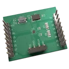
Discover the benefits of the HC32L110 microcontroller with our compact and versatile breakout board, designed to streamline development and testing for various applications. This user-friendly solution offers essential components like decoupling capacitors, a 32MHz crystal oscillator, and accessible power supply connections. The breakout board also features 0.1" pitch connectors, allowing for easy integration of I/O pins into any project. Unlock the full potential of the HC32L110B6YA-CSP16 microcontroller for rapid prototyping and smooth deployment with our ingeniously designed breakout board.
Properties
Pricing & Availability
Distributor | Qty 1 |
|---|---|
Arrow | $0.49 |
Digi-Key | $0.58–$1.17 |
LCSC | $1.32 |
Mouser | $0.61 |
Verical | $0.59 |
Controls
Welcome 👋
Flux helps you build PCBs faster with an AI teammate!
Create your account to collaborate, stay updated, fork your own version, and get instant answers from our AI agent.
docbrown
2
natarius
docbrown
natarius
docbrown
1
natarius