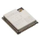
Component Pin Overview
Worked for 1 min 33 sec
From the datasheet for this module, here are the pin groups you asked for:
Bootstrap / strapping pins
These are sampled at power-up / hardware reset to set boot behavior and related configuration:
Table
| Module pin | Signal name | GPIO |
|---|---|---|
| 14 | IO12 / MTDI | GPIO12 |
| 23 | IO15 / MTDO | GPIO15 |
| 24 | IO2 | GPIO2 |
| 25 | IO0 | GPIO0 |
| 29 | IO5 | GPIO5 |
The datasheet specifically lists 5 strapping GPIOs and names them as GPIO0, GPIO2, MTDI, MTDO, and GPIO5.
Input-only pins
These are not general bidirectional GPIOs:
Table
| Module pin | Signal name | GPIO |
|---|---|---|
| 4 | SENSOR_VP | GPIO36 |
| 5 | SENSOR_VN | GPIO39 |
| 6 | IO34 | GPIO34 |
| 7 | IO35 | GPIO35 |
In the pin table, these are marked as I rather than I/O.
Pins connected to internal memory
Connected to internal SPI flash
The datasheet says GPIO6 to GPIO11 on the ESP32 chip are connected to the module’s integrated SPI flash and are not led out to module pins.
Table
| Chip GPIO | Status |
|---|---|
| GPIO6 | Connected to internal SPI flash, not led out |
| GPIO7 | Connected to internal SPI flash, not led out |
| GPIO8 | Connected to internal SPI flash, not led out |
| GPIO9 | Connected to internal SPI flash, not led out |
| GPIO10 | Connected to internal SPI flash, not led out |
| GPIO11 | Connected to internal SPI flash, not led out |
The datasheet also notes that IO16 / GPIO16 is connected to embedded PSRAM only on module variants that include embedded QSPI PSRAM. For those variants, it cannot be used for other functions.
Table
| Module pin | Signal name | GPIO | Note |
|---|---|---|---|
| 27 | IO16 | GPIO16 | Reserved only on PSRAM-equipped variants |
- No native USB pins are present
- The retrieved pin definitions do not include USB_DP, USB_DM, or any USB interface pins
- So for this module, USB is not available as a native peripheral on the module pins
- Bootstrap pins: GPIO0, GPIO2, GPIO5, GPIO12, GPIO15
- Input-only pins: GPIO34, GPIO35, GPIO36, GPIO39
- Internal flash pins: GPIO6 to GPIO11, not exposed
- USB pins: none
If you want, I can also make the next list for:
- safe general-purpose GPIOs
- ADC-capable pins
- pins to avoid during boot
List safe GPIOs
Show boot-sensitive pins
List ADC pins
Review pull resistors