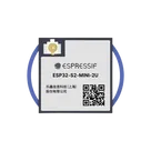
Component Pin Overview
Worked for 1 min 16 sec
I checked the Espressif datasheet and pin-definition docs for this module.
Bootstrap / strapping pins
These are the pins sampled at reset for boot/config behavior:
Table
| Pin name | Pin no. | Purpose | Default strap |
|---|---|---|---|
| GPIO0 / IO0 | 4 | Boot mode select | Weak pull-up = 1 |
| GPIO45 / IO45 | 41 | VDD_SPI voltage select | Weak pull-down = 0 |
| GPIO46 / IO46 | 44 | Boot mode / ROM message printing | Weak pull-down = 0 |
From the boot configuration tables:
- GPIO0 + GPIO46 control boot mode
- SPI boot: GPIO0 = 1, GPIO46 = don't care
- Download boot: GPIO0 = 0, GPIO46 = 0
- GPIO0 = 0, GPIO46 = 1 is an invalid combination and should be avoided.
- GPIO45 controls VDD_SPI strap behavior.
- GPIO46 also affects ROM boot message printing.
For normal GPIO use, the only input-only GPIO called out is:
Table
| Pin name | Pin no. | Notes |
|---|---|---|
| GPIO46 / IO46 | 44 | Input-only GPIO, also a strapping pin |
Also worth noting:
- EN is pin 45 and is an input used to enable/power the chip, but it is not a general-purpose GPIO.
These are the pins associated with the SPI0/1 flash/PSRAM memory interface or called out as restricted for memory use:
Direct memory-interface / reserved-use category
Table
| Pin name | Pin no. | Memory-related function |
|---|---|---|
| GPIO26 / IO26 | 26 | SPICS1; datasheet notes this pin is used by embedded PSRAM on N4R2 variants |
| GPIO33 / IO33 | 28 | SPIIO4, FSPIHD |
| GPIO34 / IO34 | 29 | SPIIO5, FSPICS0 |
| GPIO35 / IO35 | 31 | SPIIO6, FSPID |
| GPIO36 / IO36 | 32 | SPIIO7, FSPICLK |
| GPIO37 / IO37 | 33 | SPIDQS, FSPIQ |
| GPIO38 / IO38 | 34 | FSPIWP |
Important nuance:
- Espressif marks GPIO26-32 as the SPI0/1 interface used for in-package flash/PSRAM or recommended for off-package memory on the ESP32-S2 family.
- On this module’s exposed pins, you can see IO26 directly in that group.
- Espressif also says GPIO33-37 are used for the higher 4-bit data lines plus DQS in 8-line SPI mode, so they should be used with caution if that memory mode is relevant.
- The module pin table specifically notes IO26 is used by embedded PSRAM on ESP32-S2-MINI-2-N4R2 / 2U-N4R2 variants.
Yes, USB pins are present:
Table
| Pin name | Pin no. | USB function |
|---|---|---|
| GPIO19 / IO19 | 23 | USB_D- |
| GPIO20 / IO20 | 24 | USB_D+ |
- Bootstrap pins: IO0, IO45, IO46
- Input-only GPIO: IO46
- Internal-memory-related pins: IO26, IO33, IO34, IO35, IO36, IO37, IO38
- USB pins: IO19 = USB_D-, IO20 = USB_D+
If you want, I can turn this into a pin-property checklist for the part project next.
Use the attached datasheet
Add pin descriptions
Flag unavailable groups