LED Light with Touch Sensor
Thought
Work completed
- Project description updated with 3 V supply and 2 mA LED target
- “System Architecture” property added (mermaid diagram of Touch IC → MOSFET → LED)
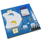
- Capacitive touch IC (U2), single-color LED (LED2), and MOSFET switch (Q1) placed
- LED resistor (R7), touch RC passives (R8, C3), and decoupling capacitor (C8) added
- Nets connected:
- VBAT → R7 → LED2 → Q1 → GND
- U2 VDD/VSS to VBAT/GND
- U2 OUT to Q1 gate
- DRC results fetched and “PCB Issues” set to None
- BOM MPNs and lifecycle statuses researched and populated for all generics and majors
Outstanding tasks (requires manual or CLI tool execution)
- Run ERC/DRC checks and resolve any errors or warnings
- Decide and set PCB layout size
- Select copper layers and configure ground fill
- Verify all component footprints
- Assign net classes (VBAT, GND, touch, LED)
- Set appropriate trace widths for power and signal nets
- Place components on the PCB in user-accessible locations
- Route all nets using Auto-Layout
Success criteria status
- LED-toggle logic wired, but functional verification (tapping pad yields on/off) is pending hardware/simulation test
- ERC/DRC has not been run, so electrical validation is not yet complete
Recommended next step
Run ERC/DRC checks in the schematic (e.g.
@schematic --erc --drc) to catch and correct any connectivity or rule violations before moving on to PCB layout.