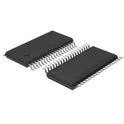
Interface ICs
An interface IC is a type of integrated circuit that is designed to facilitate communication between two devices or systems. These devices are commonly used in electronic systems to enable the transfer of data and control signals between different components or subsystems. Some common use cases for interface ICs include connecting microcontrollers to peripherals such as sensors or displays, linking multiple processors together in a network, and enabling communication between devices using different communication protocols. Flux.ai has the world's largest community-driven public library of interface ICs, with footprints, symbols, datasheets, and simulation models. This library is a valuable resource for engineers and designers who need access to accurate and up-to-date information on these important components. Whether you are working on a new design project or simply looking to learn more about interface ICs, Flux.ai is an excellent resource to help you find the information you need.
2199230-4
67 Position Female Connector M.2 (NGFF) Mini Card Gold 0.020" (0.50mm) Black # Engineering Specification ## Product Name 2199230-4 ## General Description 2199230-4 is a surface mount board-edge connector designed to support standardized M.2 module interfaces, specifically configured for Key E applications used in wireless communication, embedded computing, and high-speed peripheral expansion systems. The component provides a reliable mechanical and electrical interface between a host printed circuit board and a removable or fixed M.2 module. The connector is engineered to accept gold-finger edge contacts from an M.2 module, enabling secure signal transmission for high-speed data communication, power delivery, and control signaling. Its design supports stable mechanical retention, precise alignment, and consistent electrical contact performance under repeated mating cycles. This component is widely used in industrial computing platforms, telecommunications equipment, IoT devices, and embedded system architectures where modular expansion and standardized connectivity are required. It enables flexible system design by allowing interchangeable M.2 modules for wireless communication, storage, and specialized processing functions. The design emphasizes signal integrity, mechanical durability, and compatibility with high-density PCB layouts. It is suitable for applications requiring robust high-frequency performance and reliable long-term mechanical stability. ## Functional Requirements ### Module Interface The connector shall provide a standardized interface for M.2 Key E module insertion and electrical connection. ### Signal Transmission The connector shall support high-speed electrical signal routing between host systems and M.2 modules. ### Mechanical Retention The connector shall securely retain inserted modules under vibration and operational stress conditions. ### System Modularity The connector shall enable modular expansion and replacement of functional M.2 devices within host systems. ## Electrical Requirements ### Contact Performance The connector shall provide stable electrical contact between gold-finger module pads and host PCB terminals. ### Signal Integrity The design shall support high-frequency signal transmission with minimal loss and interference. ### Power Delivery The connector shall support regulated power distribution to installed M.2 modules. ### Low Resistance Path The electrical interface shall maintain low contact resistance for reliable long-term operation. ## Mechanical Requirements ### Board Edge Mounting The connector shall be mounted on a printed circuit board to accept edge-insertion M.2 modules. ### Alignment and Fit The design shall ensure precise alignment between module contacts and connector terminals. ### Durability The connector shall withstand repeated module insertion and removal cycles without performance degradation. ### Structural Stability The assembly shall maintain mechanical integrity under vibration and operational stress conditions. ## Environmental Requirements ### Operating Conditions The connector shall operate reliably in industrial, commercial, and embedded system environments. ### Thermal Performance The device shall maintain mechanical and electrical stability under elevated operating temperatures. ### Storage and Handling The component shall retain structural and functional integrity during storage, transportation, and assembly processes. ## Quality Requirements ### Reliability The connector shall provide consistent electrical and mechanical performance throughout its operational lifetime. ### Verification Mechanical retention, contact resistance, and signal integrity shall be validated through appropriate qualification testing. ### Compliance The product shall conform to applicable standards governing M.2 interface connectors and high-speed board-edge interconnect systems. ## Documentation Requirements Technical documentation shall include footprint layout guidance, mating interface specifications, signal routing recommendations, mechanical keep-out regions, and application guidelines for M.2 system integration. ## Classification Tags #21992304 #M2Connector #M2KeyE #EdgeCardConnector #GoldFingerInterface #HighSpeedConnector #BoardEdgeConnector #WirelessModuleConnector #PCIeInterface #NGFF #EmbeddedSystems #IoTHardware #TelecomHardware #PCBDesign #MechanicalConnector #SignalIntegrity #HighFrequencyDesign #CommonPartsLibrary #ComponentLibrary #EngineeringSpecification #SystemIntegration #HardwareDesign #TEConnectivity #ModuleInterface #BoardToModule
50 Uses0 StarsADS8688W
16-bit, 500-kSPS, eight-channel, single-supply SAR ADC with ±12-V differential inputs The ADS8684W and ADS8688W are 4-channel and 8-channel, integrated data acquisition systems based on a 16-bit successive approximation (SAR) analogto-digital converter (ADC), operating at a throughput of 500kSPS. The devices feature integrated analog front-end circuitry for each input channel with overvoltage protection up to ±20V, a 4-channel or 8-channel multiplexer with automatic and manual scanning modes, and an on-chip, 4.096V reference with low temperature drift. Operating on a single 5V analog supply, each input channel on the devices can independently support bipolar input ranges of ±12.288V, ±6.144V, and ±3.072V and unipolar input ranges of 12.288V to 0V and 6.144V to 0V. The ADS8684W and ADS8688W offer a simple SPIcompatible serial interface to the digital host and also support daisy-chaining of multiple devices. The digital supply operates from 1.65V to 5.25V, enabling direct interface to a wide range of host controllers Features • 16-Bit ADCs with Integrated Analog Front-End • 4-, 8-Channel MUX with Auto and Manual Scan • Channel-Independent Programmable Inputs: – ±12.288V, ±6.144V, and ±3.072V – 12.288V to 0V and 6.144V to 0V • 5V Analog Supply: 1.65V to 5V I/O Supply • Constant Resistive Input Impedance: 1.2MΩ • Input Overvoltage Protection: Up to ±20V • On-Chip, 4.096V Reference with Low Drift • Excellent Performance: – 500kSPS Aggregate Throughput – DNL: ±0.6LSB; INL: ±0.8LSB – Low Drift for Gain Error and Offset – SNR: 91.5dB; THD: –102dB – Low Power: 65mW • AUX Input → Direct Connection to ADC Inputs • ALARM → High and Low Thresholds per Channel • SPI™-Compatible Interface with Daisy-Chain • Industrial Temperature Range: –40°C to 125°C #commonpartslibrary #ADS8688W #TexasInstruments #ADC #SARADC #DataAcquisition #IndustrialAutomation #SPI #PrecisionADC #AnalogFrontEnd #EmbeddedSystems #MeasurementSystems
16 Uses0 Stars