Top Organization Components
Curated collection features components used in significant projects by various businesses and institutions, reflecting the current trends and high standards of the industry. From basic electronic elements to advanced modules, these components are selected for their superior quality, efficiency, and adaptability in diverse applications. It offers a glimpse into the components that are shaping the future of PCB design in professional settings. It serves as a vital resource for designers and organizations looking to stay ahead of the curve, providing insights into the component choices that lead to successful and innovative designs. By showcasing the preferred components of leading organizations, Flux.ai creates an avenue for knowledge exchange and benchmarking within the electronics design community. This subcategory is more than just a list of components; it's a reflection of industry-leading practices and a source of inspiration for those striving for excellence in PCB design.
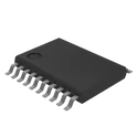
TXS0108EPWR
Voltage Level Translator Bidirectional 1 Circuit 8 Channel 60Mbps 20-TSSOP This device is an 8-bit non-inverting level translator which uses two separate configurable power-supply rails. The A port tracks the VCCA pin supply voltage. The VCCA pin accepts any supply voltage between 1.4V and 3.6V. The B port tracks the VCCB pin supply voltage. The VCCB pin accepts any supply voltage between 1.65V and 5.5V. Two input supply pins allows for low Voltage bidirectional translation between any of the 1.5V, 1.8V, 2.5V, 3.3V, and 5V voltage nodes. When the output-enable (OE) input is low, all outputs are placed in the high-impedance (Hi-Z) state. To put the device in the Hi-Z state during power-up or power-down periods, tie OE to GND through a pulldown resistor. The current-sourcing capability of the driver determines the minimum value of the resistor. • No direction-control signal needed • Maximum data rates: – 110Mbps (push pull) – 1.2Mbps (open drain) • 1.4V to 3.6V on A port and 1.65V to 5.5V on B port (VCCA ≤ VCCB) • No power-supply sequencing required – either VCCA or VCCB can be ramped first • Latch-up performance exceeds 100mA per JESD 78, class II • ESD protection exceeds JESD 22 (A port): – 2000 V Human Body Model (A114-B) – 150 V Machine Model (A115-A) – 1000 V Charged-Device Model (C101) • IEC 61000-4-2 ESD (B-port): – ± 8kV Contact Discharge – ± 6kV Air Discharge #commonpartslibrary #integratedcircuit #logic #translator #levelshifter
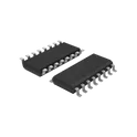
376 Uses1 StarsHX711
Precision 24-bit analog-to-digital converter (ADC) designed for weigh scales and industrial control applications to interface directly with a bridge sensor. Based on Avia Semiconductor’s patented technology, HX711 is a precision 24-bit analogto-digital converter (ADC) designed for weigh scales and industrial control applications to interface directly with a bridge sensor. The input multiplexer selects either Channel A or B differential input to the low-noise programmable gain amplifier (PGA). Channel A can be programmed with a gain of 128 or 64, corresponding to a full-scale differential input voltage of ±20mV or ±40mV respectively, when a 5V supply is connected to AVDD analog power supply pin. Channel B has a fixed gain of 32. Onchip power supply regulator eliminates the need for an external supply regulator to provide analog power for the ADC and the sensor. Clock input is flexible. It can be from an external clock source, a crystal, or the on-chip oscillator that does not require any external component. On-chip poweron-reset circuitry simplifies digital interface initialization. There is no programming needed for the internal registers. All controls to the HX711 are through the pins. • Two selectable differential input channels • On-chip active low noise PGA with selectable gain of 32, 64 and 128 • On-chip power supply regulator for load-cell and ADC analog power supply • On-chip oscillator requiring no external component with optional external crystal • On-chip power-on-reset • Simple digital control and serial interface: pin-driven controls, no programming needed • Selectable 10SPS or 80SPS output data rate • Simultaneous 50 and 60Hz supply rejection • Current consumption including on-chip analog power supply regulator: normal operation < 1.5mA, power down < 1uA • Operation supply voltage range: 2.6 ~ 5.5V • Operation temperature range: -40 ~ +85℃ • 16 pin SOP-16 package #commonpartslibrary #integratedcircuit #analog #digital #converter #sensor
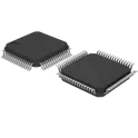
805 Uses1 StarsSTM32F405RGT6
ARM® Cortex®-M4 series Microcontroller IC 32-Bit Single-Core 168MHz 1MB (1M x 8) FLASH 64-LQFP (10x10) Arm® Cortex®-M4 32b MCU+FPU, 210DMIPS, up to 1MB flash/192+4KB RAM, USB OTG HS/FS, Ethernet, 17 TIMs, 3 ADCs, 15 comm. interfaces, and camera Includes ST state-of-the-art patented technology • Core: Arm® 32-bit Cortex®-M4 CPU with FPU, Adaptive real-time accelerator (ART Accelerator) allowing 0-wait state execution from flash memory, frequency up to 168 MHz, memory protection unit, 210 DMIPS/ 1.25 DMIPS/MHz (Dhrystone 2.1), and DSP instructions • Memories – Up to 1 Mbyte of flash memory – Up to 192+4 Kbytes of SRAM including 64- Kbyte of CCM (core coupled memory) data RAM – 512 bytes of OTP memory – Flexible static memory controller supporting CompactFlash™, SRAM, PSRAM, NOR and NAND memories • LCD parallel interface, 8080/6800 modes • Clock, reset, and supply management – 1.8 V to 3.6 V application supply and I/Os – POR, PDR, PVD and BOR – 4-to-26 MHz crystal oscillator – Internal 16 MHz factory-trimmed RC (1% accuracy) – 32 kHz oscillator for RTC with calibration – Internal 32 kHz RC with calibration • Low-power operation – Sleep, Stop, and Standby modes –VBAT supply for RTC, 20×32-bit backup registers + optional 4 KB backup SRAM • 3×12-bit, 2.4 MSPS A/D converters: up to 24 channels and 7.2 MSPS in triple interleaved mode • 2×12-bit D/A converters • General-purpose DMA: 16-stream DMA controller with FIFOs and burst support • Up to 17 timers: up to twelve 16-bit and two 32- bit timers up to 168 MHz, each with up to 4 IC/OC/PWM or pulse counter and quadrature (incremental) encoder input • Debug mode – Serial wire debug (SWD) & JTAG interfaces – Cortex-M4 Embedded Trace Macrocell™ • Up to 140 I/O ports with interrupt capability – Up to 136 fast I/Os up to 84 MHz – Up to 138 5 V-tolerant I/Os • Up to 15 communication interfaces – Up to 3 × I2C interfaces (SMBus/PMBus) – Up to 4 USARTs/2 UARTs (10.5 Mbit/s, ISO 7816 interface, LIN, IrDA, modem control) – Up to 3 SPIs (42 Mbits/s), 2 with muxed full-duplex I2S to achieve audio class accuracy via internal audio PLL or external clock – 2 × CAN interfaces (2.0B Active) – SDIO interface • Advanced connectivity – USB 2.0 full-speed device/host/OTG controller with on-chip PHY – USB 2.0 high-speed/full-speed device/host/OTG controller with dedicated DMA, on-chip full-speed PHY and ULPI – 10/100 Ethernet MAC with dedicated DMA: supports IEEE 1588v2 hardware, MII/RMII #commonpartslibrary #integratedcircuit #microcontroller
63 Uses1 StarsSentinels Hub Air Hex test 2
Sentinels Hub Air Hex Rev B: matte-black point-top hex 3.3 V I2C environmental sensor breakout with BME690/BME688-compatible footprint, dual Qwiic connectors, protected I2C bus, selectable address, PU_EN pullups, optional DNI SHT45 Pro area, IPC Class 3 manufacturing intent.
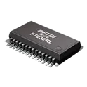
0 Uses1 StarsFT232RL
USB to Serial Interface, SSOP-28 FTDI USB Serial SSOP*5.3x10.2mm*P0.65mm* The FT232RL is a full-speed USB 2.0 to asynchronous serial data transfer IC. It integrates all the necessary USB protocol handling and UART interface logic, making it very easy to add USB connectivity to embedded devices without requiring complex firmware development. It is commonly used in development boards (like Arduino clones), USB-to-TTL converters, and debugging interfaces. Key Features USB Interface Fully compliant with USB 2.0 Full-Speed (12 Mbps) Integrated USB transceiver (no external components required) Supports USB suspend/resume modes Internal EEPROM for storing USB descriptors (no external EEPROM needed) Serial (UART) Interface Supports standard UART communication (TX, RX) Configurable baud rates from 300 bps up to 3 Mbps Supports hardware flow control (RTS/CTS, DTR/DSR) Bit-bang mode for simple GPIO control Integrated Components Built-in clock generator (no external crystal required) Internal EEPROM for configuration Integrated voltage regulator (3.3V output available for external use) Power Features Operates from 3.3V to 5V Can be powered directly from USB (bus-powered) Low power consumption with sleep mode Driver Support Virtual COM Port (VCP) drivers available for: Windows Linux macOS Also supports direct D2XX driver for advanced applications Package Typically available in SSOP-28 package Common Applications USB-to-serial converters (TTL/RS232) Microcontroller programming and debugging Embedded system communication Industrial and instrumentation interfaces
157 Uses1 StarsPeakNode 1
Ruggedized battery-powered PeakNode 1 LoRa PWAN node with SX1262 LoRa mesh over SPI, LTE Cat-M1/NB-IoT modem, GNSS, LPCNet-capable audio path, USB-C charging and LiFePO4 power management. Targets a 4-layer 90 mm x 60 mm IPC Class 2 layout with 3.3 V main and 1.8 V I/O rails, dual SMA antennas, two RGB status LEDs, three tactile buttons, low-leakage power architecture for sub-10 uA sleep, and defined RF keep-out zones under the LoRa and LTE antenna regions.
0 Uses1 StarsMini UPS 42V to 12V
Mini UPS PCB for a 42 V external adapter and external 10S lithium battery pack. Includes adapter-priority source selection with automatic switchover, input protection, ideal-diode OR-ing, a 30 V to 42 V HV bus, and a regulated 12 V output stage. Includes status LEDs and battery monitor pads. Excludes onboard charger circuitry and excludes adapter or battery source design.
0 Uses1 StarsADXL335BCPZ
Accelerometer X, Y, Z Axis ±3g 1.6kHz (X,Y), 550Hz (Z) 16-LFCSP-LQ (4x4) The ADXL335BCPZ is a small, thin, low-power, complete 3-axis accelerometer with signal-conditioned voltage outputs. It measures acceleration with a minimum full-scale range of ±3 g. The device outputs analog voltages proportional to acceleration in each of the three orthogonal axes (X, Y, and Z). The accelerometer is designed for low power consumption and high resolution, making it suitable for mobile devices, tilt sensing, motion detection, and vibration monitoring. It operates over a wide temperature range and requires minimal external components, enabling easy integration into compact systems. Functional Overview The ADXL335 uses a capacitive sensing structure to detect acceleration. Changes in acceleration result in differential capacitance changes, which are converted into voltage outputs through an internal signal conditioning circuit. Each axis provides an independent analog output that can be directly interfaced with ADC inputs of microcontrollers or other processing units. Bandwidth for each axis can be adjusted using external capacitors, allowing flexibility depending on application requirements. Electrical Characteristics Supply Voltage Range: 1.8 V to 3.6 V Supply Current: Typical: 350 µA Measurement Range: ±3 g Sensitivity (Typical): 300 mV/g Zero-g Bias Level: Approximately mid-supply voltage Bandwidth: User-selectable via external capacitors Typical range: X, Y axes: up to 1600 Hz Z axis: up to 550 Hz Output Characteristics Output Type: Analog voltage (ratiometric to supply voltage) Number of Axes: Three (X, Y, Z) Output Noise: Low noise suitable for precision motion sensing Cross-Axis Sensitivity: Typically ±1% Mechanical Characteristics Package Type: 16-lead LFCSP (Lead Frame Chip Scale Package) Dimensions: Approximately 4 mm × 4 mm × 1.45 mm Mounting: Surface mount Environmental Specifications Operating Temperature Range: −40°C to +85°C Shock Survivability: Up to 10,000 g Interface Requirements External Components: Requires capacitors for bandwidth setting (one per axis) Output Interface: Direct analog output compatible with ADC inputs Applications Mobile devices and handheld electronics Tilt and orientation sensing Vibration monitoring systems Gaming and motion input devices Industrial instrumentation Wearable electronics Key Features Low power consumption Compact form factor High resolution analog outputs User-adjustable bandwidth Wide operating temperature range Simple integration with minimal external components #commonpartslibrary #sensor #transducer #motionsensor #accelerometer
58 Uses1 StarsESP32 Robot Controller | AI Design Review Tutorial [Example]
Spot the mistake! Learn how to use AI to conduct a design review on an ESP32-based control board. This project is ideal for autonomous or radio-controller robots featuring inputs for sensors, encoders, and a Flysky RC receiver, plus an I2C display for configuration.
0 Uses1 StarsPCB Business Card V2
Change History from V1: -13.56MHz tuning -larger instruction font -put some stuff on the back #template I wanted to create a business card that has some functionality and shows off a bit of my portfolio IRL: -NFC to my flux page -here's the [instructables](https://www.instructables.com/PCB-Business-Card-With-NFC-Make-Yours-With-NFC-QR-/) -Put a bunch of modules on it Find the BoM [here](https://www.digikey.com/short/2db2vnmp)
0 Uses1 Stars




![ESP32 Robot Controller | AI Design Review Tutorial [Example]](https://img-cdn.flux.ai/eyJidWNrZXQiOiJncmF2aXRvbi1lbGVjdHJpYy1zeW1ib2xzIiwia2V5IjoiZG9jdW1lbnRfYXNzZXRzL1RodW1ibmFpbC1FU1AzMi0tMS0tZTNjNjM0OGEtYjEzMy00YjliLWEyYTItMzY1MGNiMjgyYWJiLnBuZyIsImVkaXRzIjp7InJlc2l6ZSI6eyJ3aWR0aCI6MTI0LCJoZWlnaHQiOjEyNCwiZml0IjoiY29udGFpbiIsImJhY2tncm91bmQiOnsiciI6MCwiZyI6MCwiYiI6MCwiYWxwaGEiOjB9fX0sIm91dHB1dEZvcm1hdCI6IndlYnAifQ==)