• Awful Blush Transporter

    Awful Blush Transporter

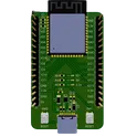
    Production-ready ESP32-based HDMI + USB 8-bit gaming console using ESP32-WROOM-32E, ADV7513BSWZ HDMI transmitter, FT232RL USB bridge, W25Q32JV external flash, LMR50410 buck regulator, and TLV75801 LDO, with full decoupling, ESD protection, TMDS termination, HDMI/USB/power/programming connectors, buttons, LEDs, and audio, optimized for JLCPCB PCBA #ESP32 #HDMI #USB #GamingConsole #SchoolProject

    berke5

    7 months ago

    0 Uses

    0 Comments

    0 Stars


  • Costly Ivory Mr. Fusion

    Costly Ivory Mr. Fusion

    Relay HAT Schematic – Post‑Validation Fix Plan (ULN2803A, Buck → Pico, LEDs, Optos, Testpoints)

    9 months ago

    0 Uses

    0 Comments

    0 Stars


  • On Air R2 Demo

    On Air R2 Demo

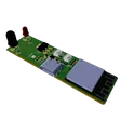
    Daddy's second circuit board. A sign to let my wife know when I'm on a call. Activates with a slide switch and is powered by USB-C. R2 changes: -Moving to Letter Modules for ease of design -Adding ESP32 for WiFi On/Off and intensity control -Optional: Add unpopulated AA Battery Holder for battery option R1 changes: -Changed LED part to Red LEDs -adjusted resistor value of buck converter -Changed source for USB-C Connector -Removed exposed soldermask on buck converter with negative soldermask expansion -Order with black soldermask Modified by markwu2001: Adjustable Brightness, 85-90% Drive Efficiency <5W Operation (Can use 5V 1A Plug) This project can be purchased from LCSC

    10 months ago

    0 Uses

    0 Comments

    0 Stars


  • ESP32-S3-WROOM-1 Reference Design c6gD

    ESP32-S3-WROOM-1 Reference Design c6gD

    This project is a reference project for ESP32-S3-WROOM-1 to develop your IoT ideas. The board has 3 LEDs, USB C for firmware, EN and BOOT buttons, and 2 IO connectors for development #IoT #WiFi #MCU #RF #ESP32 #project #referenceDesign #simple-embedded #espressif #template #reference-design

    a year ago

    0 Uses

    0 Comments

    0 Stars


  • WiFi to IR Gateway Reference Design bN3H

    WiFi to IR Gateway Reference Design bN3H

    This is a WiFi to Infrared (IR) gateway reference design leveraging an ESP32-S3 microcontroller for WiFi connectivity. It also incorporates a Type-C USB interface for data and power, 3 LEDs (red, green, & IR), and voltage regulation. It facilitates wireless control of IR devices, suitable for home automation projects. #referenceDesign #edge-computing #espressif #template #IR #project #reference-design

    a year ago

    0 Uses

    0 Comments

    0 Stars


  • ESP32-S3-WROOM-1 Reference Design

    ESP32-S3-WROOM-1 Reference Design

    This project is a reference project for ESP32-S3-WROOM-1 to develop your IoT ideas. The board has 3 LEDs, USB C for firmware, EN and BOOT buttons, and 2 IO connectors for development #IoT #WiFi #MCU #RF #ESP32 #project #referenceDesign #simple-embedded #espressif #template #reference-design

    a year ago

    0 Uses

    0 Comments

    0 Stars


  • KEY PAD x 24 v3 ANGOSTO c914 e3bd

    KEY PAD x 24 v3 ANGOSTO c914 e3bd

    This module involves the design of a keypad lock system. It utilizes an ATMEGA328P microcontroller, buzzers, LEDs for indicator functions and a 4x3 matrix keypad. An in-circuit serial programming (ISP) header is also present for programming the microcontroller. #template #lock #keypad #reusable #module #simple-embedded #microchip #arduino #atmega328 #TPS613222A #ISP #buzzer #sublayout

    a year ago

    0 Uses

    0 Comments

    0 Stars


  • ESP32-S3-WROOM-1 Reference Design

    ESP32-S3-WROOM-1 Reference Design

    This project is a reference project for ESP32-S3-WROOM-1 to develop your IoT ideas. The board has 3 LEDs, USB C for firmware, EN and BOOT buttons, and 2 IO connectors for development #IoT #WiFi #MCU #RF #ESP32 #project #referenceDesign #simple-embedded #espressif #template #reference-design

    a year ago

    0 Uses

    0 Comments

    0 Stars


  • KEY PAD x 24 v3 ANGOSTO 959d

    KEY PAD x 24 v3 ANGOSTO 959d

    This module involves the design of a keypad lock system. It utilizes an ATMEGA328P microcontroller, buzzers, LEDs for indicator functions and a 4x3 matrix keypad. An in-circuit serial programming (ISP) header is also present for programming the microcontroller. #template #lock #keypad #reusable #module #simple-embedded #microchip #arduino #atmega328 #TPS613222A #ISP #buzzer #sublayout

    a year ago

    0 Uses

    0 Comments

    0 Stars


  • KEY PAD x 24 v4 ANGOSTO

    KEY PAD x 24 v4 ANGOSTO

    This module involves the design of a keypad lock system. It utilizes an ATMEGA328P microcontroller, buzzers, LEDs for indicator functions and a 4x3 matrix keypad. An in-circuit serial programming (ISP) header is also present for programming the microcontroller. #template #lock #keypad #reusable #module #simple-embedded #microchip #arduino #atmega328 #TPS613222A #ISP #buzzer #sublayout

    8 months ago

    0 Uses

    0 Comments

    0 Stars


  • ESP32-S3-WROOM-1 Reference Design

    ESP32-S3-WROOM-1 Reference Design

    This project is a reference project for ESP32-S3-WROOM-1 to develop your IoT ideas. The board has 3 LEDs, USB C for firmware, EN and BOOT buttons, and 2 IO connectors for development #IoT #WiFi #MCU #RF #ESP32 #project #referenceDesign #simple-embedded #espressif #template #reference-design

    a year ago

    0 Uses

    0 Comments

    0 Stars


  • Programmable LED Ring ded2

    Programmable LED Ring ded2

    Ring of LEDs controlled by an STM32 Microcontroller so that I can learn to program microcontrollers.

    a year ago

    0 Uses

    0 Comments

    0 Stars


  • ESP32-S3-WROOM-1 Reference Design

    ESP32-S3-WROOM-1 Reference Design

    This project is a reference project for ESP32-S3-WROOM-1 to develop your IoT ideas. The board has 3 LEDs, USB C for firmware, EN and BOOT buttons, and 2 IO connectors for development #IoT #WiFi #MCU #RF #ESP32 #project #referenceDesign #simple-embedded #espressif #template #reference-design

    a year ago

    0 Uses

    0 Comments

    0 Stars


  • AVTheremin_v02 BRANCH 1

    AVTheremin_v02 BRANCH 1

    BRANCH 1 ESP32 + Sensors + LEDs + USB-C

    +

    U

    a month ago

    0 Uses

    0 Comments

    0 Stars


  • ESP32-S3-WROOM-1 Reference Design

    ESP32-S3-WROOM-1 Reference Design

    This project is a reference project for ESP32-S3-WROOM-1 to develop your IoT ideas. The board has 3 LEDs, USB C for firmware, EN and BOOT buttons, and 2 IO connectors for development #IoT #WiFi #MCU #RF #ESP32 #project #referenceDesign #simple-embedded #espressif #template #reference-design

    a year ago

    0 Uses

    0 Comments

    0 Stars


  • ESP32-S3-WROOM-1 Reference Design

    ESP32-S3-WROOM-1 Reference Design

    This project is a reference project for ESP32-S3-WROOM-1 to develop your IoT ideas. The board has 3 LEDs, USB C for firmware, EN and BOOT buttons, and 2 IO connectors for development #IoT #WiFi #MCU #RF #ESP32 #project #referenceDesign #simple-embedded #espressif #template #reference-design

    a year ago

    0 Uses

    0 Comments

    0 Stars


  • Secret Crimson Hoverboard

    Secret Crimson Hoverboard

    Circuit Overview The circuit you're describing is a digital counter that uses an LDR (Light-Dependent Resistor) and a transistor to detect wheel rotations. The counter's output is then displayed on a seven-segment LED display. Here's a breakdown of the components and their roles: 1. Wheel Rotation Detection (LDR and Transistor) * LDR: The LDR acts as a sensor to detect changes in light intensity. You can mount it on the wheel' or near it, with a reflective or non-reflective surface attached to the wheel. As the wheel rotates, the LDR will be exposed to alternating light and dark conditions, causing its resistance to change. * Transistor: The transistor (e.g., a 2N2222 NPN BJT) is used as a switch or amplifier. The changing resistance of the LDR is used to control the base current of the transistor. When the LDR's resistance drops (more light), the transistor turns on, and when the resistance increases (less light), the transistor turns off. This converts the analog change in light into a digital ON/OFF signal (a pulse). 2. Counter (7490) * 7490 IC: This is a decade counter, meaning it can count from 0 to 9. The output of the transistor (the pulses) is fed into the clock input of the 7490. Each pulse represents one rotation of the wheel, and the 7490 increments its count accordingly. The 7490 has four outputs (Q0, Q1, Q2, Q3) that represent the BCD (Binary-Coded Decimal) equivalent of the count. 3. BCD to Seven-Segment Decoder (7446) * 7446 IC: The 7446 is a BCD-to-seven-segment decoder/driver. Its job is to take the 4-bit BCD output from the 7490 and convert it into a signal that can drive a seven-segment LED display. It has seven outputs (a, b, c, d, e, f, g), each corresponding to a segment of the LED display. 4. Seven-Segment LED Display * Seven-Segment Display: This display is used to show the count. The 7446's outputs are connected to the corresponding segments of the display. 5. Power Supply and Other Components * Power Supply: A regulated DC power supply (e.g., 5V) is needed to power all the ICs and components. * Resistors: Resistors are used for current limiting (e.g., for the LDR and the LED display) and biasing the transistor. * Capacitors: A capacitor might be used for debouncing the signal from the transistor to prevent multiple counts for a single rotation. Conceptual Connections Here is a step-by-step breakdown of how the components would be connected: * LDR and Transistor: * The LDR and a current-limiting resistor are connected in series across the power supply. * The junction between the LDR and the resistor is connected to the base of the NPN transistor. * The emitter of the transistor is connected to ground. * The collector of the transistor, with a pull-up resistor, becomes the output for the pulse signal. * Transistor to 7490: * The output from the transistor's collector is connected to the clock input of the 7490 IC. * The 7490's reset pins (MR and MS) should be connected to ground for normal counting operation. * 7490 to 7446: * The BCD outputs of the 7490 (Q0, Q1, Q2, Q3) are connected to the BCD inputs of the 7446 (A, B, C, D). * 7446 to Seven-Segment Display: * The outputs of the 7446 (a, b, c, d, e, f, g) are connected to the corresponding segments of the seven-segment display. * Crucially, you need to use current-limiting resistors (e.g., 330Ω) in series with each segment to protect the LEDs from high current. * The common terminal of the seven-segment display is connected to the power supply (for a common anode display) or ground (for a common cathode display). This setup creates a chain reaction: wheel rotation changes light, which changes LDR resistance, which turns the transistor on/off, generating a pulse. This pulse increments the 7490, and the 7490's output is decoded by the 7446, which then displays the count on the seven-segment LED.

    a year ago

    0 Uses

    0 Comments

    0 Stars


  • Portable Audio DSP - Unrouted 09ae jfUa

    Portable Audio DSP - Unrouted 09ae jfUa

    Portable Audio DSP project utilizing multiple ICs, capacitors, resistors, and LEDs for advanced audio processing and control. Designed for embedded audio applications with ESP32, ADC, DAC, and interface components. #audioDevices #DSP #ADC #audio #DAC

    a year ago

    0 Uses

    0 Comments

    0 Stars


  • Portable Audio DSP - Unrouted 09ae jfUa

    Portable Audio DSP - Unrouted 09ae jfUa

    Portable Audio DSP project utilizing multiple ICs, capacitors, resistors, and LEDs for advanced audio processing and control. Designed for embedded audio applications with ESP32, ADC, DAC, and interface components. #audioDevices #DSP #ADC #audio #DAC

    a year ago

    0 Uses

    0 Comments

    0 Stars


  • Portable Audio DSP - Unrouted

    Portable Audio DSP - Unrouted

    Portable Audio DSP project utilizing multiple ICs, capacitors, resistors, and LEDs for advanced audio processing and control. Designed for embedded audio applications with ESP32, ADC, DAC, and interface components. #audioDevices #DSP #ADC #audio #DAC

    a year ago

    0 Uses

    0 Comments

    0 Stars


  • Letter R Module Addressable

    Letter R Module Addressable

    Letter R set of WS2812B-2020 LEDs

    a year ago

    0 Uses

    0 Comments

    0 Stars


  • Portable Audio DSP - Unrouted 09ae

    Portable Audio DSP - Unrouted 09ae

    Portable Audio DSP project utilizing multiple ICs, capacitors, resistors, and LEDs for advanced audio processing and control. Designed for embedded audio applications with ESP32, ADC, DAC, and interface components. #audioDevices #DSP #ADC #audio #DAC

    a year ago

    0 Uses

    0 Comments

    0 Stars


  • ESP32-S3-WROOM-1 Reference Design 9bff

    ESP32-S3-WROOM-1 Reference Design 9bff

    This project is a reference project for ESP32-S3-WROOM-1 to develop your IoT ideas. The board has 3 LEDs, USB C for firmware, EN and BOOT buttons, and 2 IO connectors for development #IoT #WiFi #MCU #RF #ESP32 #project #referenceDesign #simple-embedded #espressif #template #reference-design

    a year ago

    0 Uses

    0 Comments

    0 Stars


  • Magic Ring

    Magic Ring

    A board with an array of LEDs that are controlled via STM32, and there is also an accelerometer and a temperature sensor! #stm32 #iot #magic #led

    a year ago

    0 Uses

    0 Comments

    0 Stars


  • ESP32-S3-WROOM-1 Reference Design

    ESP32-S3-WROOM-1 Reference Design

    This project is a reference project for ESP32-S3-WROOM-1 to develop your IoT ideas. The board has 3 LEDs, USB C for firmware, EN and BOOT buttons, and 2 IO connectors for development #IoT #WiFi #MCU #RF #ESP32 #project #referenceDesign #simple-embedded #espressif #template #reference-design

    a year ago

    0 Uses

    0 Comments

    0 Stars


Previous

Page 11 of 16

Next