Datasheet Review and Verification
Thought for 8 sec
I’ll review the part metadata and existing symbol/footprint, find the official datasheet if missing, update the Datasheet property, then cross-check pins and summarize mismatches.
Thought for 48 sec
I found the official Tensility product page and PDF datasheet; I’ll add the datasheet URL and finish the mechanical/pin review now.
Worked for 2 mins 26 sec
Completed the Tensility 54-00248 review and created the report: Part Datasheet Cross-Check: Tensility 54-00248.
Open items:
- I recorded the official datasheet URL in
Implementation Detailsbecause the available project-property editor did not expose a dedicatedDatasheet URLfield. - Main issues flagged: missing pin descriptions, sparse part metadata, and a footprint unit-display caution to verify before manufacturing.
Suggested next steps:
- Add generic pin descriptions for pins 1–8 and S1.
- Populate searchable part metadata like manufacturer, connector type, current/voltage rating, and contact count.
- Run/export a manufacturing drill/pad check to confirm the footprint dimensions.
Fix metadata and verify
Add pin descriptions
Populate part metadata
Verify footprint export
Check official PDF visually
Refine this doc
Ask about this doc
Part Datasheet Cross-Check: Tensility 54-00248
Reviewed project part information
- Project/part name:
54-00248 - Manufacturer Part Number:
54-00248 - Manufacturer: Tensility International Corporation (from official product page)
- Published Flux part UID:
eab7c779-cc18-4da4-922b-5393d7f44100 - Existing project description:
A1 Manufacturer Recommendations 16mm Tensility - Existing project-level properties before review:
Manufacturer Part Number: 54-00248,Designator Prefix: J - Datasheet URL added under project
Implementation Details:https://tensility.s3.us-west-2.amazonaws.com/uploads/pdffiles/54-00248.pdf - Official product page:
https://www.tensility.com/products/54-00248
Note: Flux project properties available to the mutation tool did not expose a dedicated
Datasheet URL project-level field, so the official datasheet URL was recorded in Implementation Details.Official key specs from Tensility
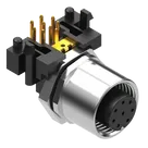
- Description: Connector, M12 A-code socket, 8 pin, 12 × L23.4 mm, panel mount, thru hole, 90°, board lock, gold plated, IP67.
- Connector family/type: M series, M12.
- Style/gender: jack/socket, female socket contacts.
- Coding: A-code.
- Contact count: 8 signal contacts.
- Shield: shielded shell contact shown.
- Mounting/package style: rear panel mount, right-angle PCB thru-hole, board-lock mechanical retention.
- Voltage rating: 30 V.
- Current rating: 2.0 A.
- Operating temperature: -40 to +105 °C.
- Mating cycles: 500 minimum.
- Environmental rating: IP67 in mated state; panel ingress requires sealing cap per datasheet note.
- Materials: PA66 insulator, brass/gold-plated pins, brass/nickel-plated shell, silicone rubber O-ring.
- Electrical test specs: dielectric strength 500 Vac for 1 minute; insulation resistance 100 MΩ at 500 Vdc; contact resistance listed as 10 MΩ or less in the extracted datasheet text, likely intended as 10 mΩ or less but should be verified visually in the PDF.
Schematic symbol cross-check
Current symbol terminals
The Flux part currently contains 9 schematic terminal components:
Table
| Symbol terminal | Pin Number property | Pin Type | Notes |
|---|---|---|---|
1 | 1 | Passive | Present |
2 | 2 | Passive | Present |
3 | 3 | Passive | Present |
4 | 4 | Passive | Present |
5 | 5 | Passive | Present |
6 | 6 | Passive | Present |
7 | 7 | Passive | Present |
8 | 8 | Passive | Present |
SHELL | S1 | Passive | Present; shield/shell terminal |
Symbol result
- Contact count matches the datasheet: 8 signal contacts plus shell/shield.
- Pin numbering matches the datasheet-level contact numbering: 1 through 8 plus shell.
- Pin electrical type is acceptable as
Passivefor a connector. - Mismatch / incomplete metadata: individual terminals have no
Pin Descriptiontext. Datasheet does not provide signal functions, so recommended descriptions are generic contact labels such asM12 A-code contact 1throughM12 A-code contact 8, andShield / shellfor S1. - Mismatch / metadata gap: project-level properties do not currently include manufacturer name, connector type, contact count, package/mounting style, voltage/current ratings as part-specific searchable properties except the voltage/temperature entries added during this review.
Footprint cross-check
Current footprint details found
The imported KiCad footprint
TENSILITY_54-00248.kicad_mod contains:- Signal/contact plated thru-hole pads:
- Pin 1 at (-1.5, -2.1), 1.4 mm pad, 1.0 mm drill, rectangular.
- Pin 2 at (1.5, -2.1), 1.4 mm pad, 1.0 mm drill.
- Pin 3 at (2.725, 0.0), 1.4 mm pad, 1.0 mm drill.
- Pin 4 at (2.075, 2.1), 1.4 mm pad, 1.0 mm drill.
- Pin 5 at (0.0, 2.1), 1.4 mm pad, 1.0 mm drill.
- Pin 6 at (-2.075, 2.1), 1.4 mm pad, 1.0 mm drill.
- Pin 7 at (-2.725, 0.0), 1.4 mm pad, 1.0 mm drill.
- Pin 8 at (0.0, 0.0), 1.4 mm pad, 1.0 mm drill.
- Shell plated thru-hole pad:
- S1 at (0.0, 4.0), 1.7 mm pad, 1.3 mm drill.
- Mechanical NPTH board-lock holes:
- Four unnumbered NPTH holes at (±7.5, 0.0) diameter 2.3 mm and (±7.5, 4.0) diameter 2.8 mm.
- Footprint outline includes panel edge marking, fab/silk geometry, courtyard, and pin 1 marker.
Footprint result
- Signal pad count matches the datasheet: 8 × Ø1.0 mm through-holes.
- Shell pad is present and matches the datasheet concept of a shield/shell connection.
- Board-lock/mechanical holes are present and match the expected four unconnected mechanical holes.
- Pad coordinates are consistent with the datasheet dimensions extracted for 2.1 mm vertical spacing, 4.15/5.45 mm horizontal spread references, and 16 mm board-lock spacing.
- The footprint appears imported in meters internally in the layout tree, but the KiCad asset payload is in millimeters and is the authoritative footprint source in this part.
- Mismatch / caution: the current layout tree reports computed pad positions such as
x: 0.0015and sizes such as0.0014underunit: mm; this appears to be unit-scaled display data from the importer, while the embedded KiCad footprint payload correctly shows mm dimensions. Verify generated manufacturing output before release. - Mismatch / caution: the NPTH pads are named
None; this is acceptable for unconnected mechanical holes, but if the platform expects unique mechanical pad names, rename them or ensure DRC/export handles them correctly.
Flagged mismatches and recommended fixes
-
Datasheet URL was missing as a dedicated part property.
- Action taken: recorded official datasheet URL in project
Implementation Detailsbecause the available project-property mutation interface did not expose a dedicatedDatasheet URLproperty. - Recommended follow-up: if Flux exposes the published-part
Datasheet URLfield in the part editor UI, set it there ashttps://tensility.s3.us-west-2.amazonaws.com/uploads/pdffiles/54-00248.pdfor the product-page PDF linkhttps://tensility.s3.us-west-2.amazonaws.com/imports/product_spec_sheets/54-00248.pdf.
- Action taken: recorded official datasheet URL in project
-
Pin descriptions are missing.
- Recommended follow-up: add
Pin Descriptionvalues: pins 1–8 asM12 A-code contact N; S1 asShield / shell.
- Recommended follow-up: add
-
Part metadata is sparse.
- Recommended follow-up: add searchable component/part metadata where supported: Manufacturer Name = Tensility International Corporation; Connector Type = M12 A-code socket; Connector Gender = Socket / female; Connector Positions = 8; Mount = Through Hole / Panel Mount; Package = right-angle panel-mount circular connector; Current Rating = 2 A; Voltage Rating = 30 V; Operating Temperature = -40 to 105 °C; IP rating = IP67 if supported.
-
Contact resistance extraction ambiguity.
- The web/PDF extraction returned
10 MΩ or less, which is unusual for contact resistance and likely means10 mΩ or less. Verify visually against the official PDF before entering that spec as a property.
- The web/PDF extraction returned
-
Footprint unit-display caution.
- Embedded KiCad footprint dimensions are correct-looking in mm, but Flux layout tree displayed small decimal meter-like values while labeling unit as mm. Exported drill/pad data should be checked before manufacturing.
Overall conclusion
The core symbol and footprint structure match Tensility 54-00248: 8 numbered connector contacts, one shell/shield pad, right-angle through-hole footprint, and board-lock mechanical holes. The main gaps are metadata completeness, missing pin descriptions, and the need to set the official datasheet URL in the dedicated published-part datasheet field if the UI/tooling exposes it.
Reviewed project part information
Official key specs from Tensility
Schematic symbol cross-check
Current symbol terminals
Symbol result
Footprint cross-check
Current footprint details found
Footprint result
Flagged mismatches and recommended fixes
Overall conclusion