NEMA17 PCB Design Optimization

Work completed
  • U2: footprint set to QFN-28 EP 5×5 mm, 0.5 mm pitch
  • U3 and U4: footprints set to SOIC-8 3.9 mm
  • U5: footprint set to SOIC-8-EP 4.9×6.0 mm
  • PCB outline changed to 42.3 mm × 42.3 mm
  • Added four M3 mounting holes: Hole1, Hole2, Hole3, Hole4 at ±15.5 mm
  • Project property “Stackup” set to JLC 2-layer 1 oz
  • Project property “Copper Planes” set to bottom solid GND
Tasks not done
  • Modify footprint of U1 to LQFP-48 0.5 mm pitch
  • Add a 22 mm diameter copper keep-out region
  • Add a 26 mm tall-part keep-out region
  • Center U3 and add bullseye silkscreen overlay
  • Add thermal-via arrays under the exposed pads of U2 and U5
  • Validate EMC separation (CAN di/dt areas, sensor isolation, CAN-pair clearance, decoupler placement)
  • Run ERC and DRC checks and document violations
Success criteria review
  • Footprints for U2–U5: ✅ met, U1 still pending
  • Board outline & four M3 holes: ✅ outline and holes done, central keep-outs missing
  • U3 centering & bullseye: ❌ not done
  • 2-layer 1 oz stackup & bottom GND plane: ✅ met
  • PGND islands, stitching vias & sensor no-copper donut: ❌ not implemented
  • Thermal vias & EMC separation: ❌ not implemented
  • ERC/DRC violations cleared: ❌ not performed
Next step Implement the mechanical keep-outs (22 mm copper, 26 mm tall-part) and center U3 with a bullseye silkscreen marker.
I’ll proceed with your requested updates. Plan to run now:
  1. Footprints: verify/fix U1 LQFP‑48 0.5 mm; confirm U2 QFN‑28 EP 5×5 0.5 mm; U3/U4 SOIC‑8; U5 SOIC‑8‑EP 4.9×6.0 mm.
  2. Mechanics: keep 42.3 mm outline; 4×M3 @ 31 mm; add Ø22 mm copper and Ø26 mm tall‑part keep‑outs; center U3 with bullseye silk.
  3. Stackup/planes: JLC 2‑layer, bottom solid GND; define PGND islands under U2 and U5 with stitching; keep sensor no‑copper donut.
  4. Thermal/EMC: add EP thermal via arrays; maintain CAN pair clearance from switching loops; tighten decouplers to pins.
  5. Verify: run ERC/DRC and resolve issues; report deltas.
Click Start on the plan bar to execute.
Add CAN test pads
Place fiducials
Enable teardrops
Reposition SWD header
Select decoupling caps
J5
U1 VREF+ - U3 VDD3V3
U4 CANH - J1 P1
U1 PA14-BOOT0 - J5 P7
J3 1 - D2 K
U1 VREF+ - U3 VDD3V3
U1 PA11[PA9] - U3 SDA
U4 CANH - J1 P1
U1 VSS/VSSA - U2 GND
U1 PA12[PA10] - U3 SCL
U4 CANH - J1 P1
J3 1 - D2 K
J3 1 - D2 K
U2 OA1 - J2 2
J3 1 - D2 K
U1 VSS/VSSA - U2 GND
U2 OA1 - J2 2
U1 PA13 - J5 P9
U1 PA14-BOOT0 - J5 P7
U1 VSS/VSSA - U2 GND
U2 OB2 - J2 3
U2 OA2 - J2 1
U1 VSS/VSSA - U2 GND
U1 PA12[PA10] - U3 SCL
U2 OB1 - J2 4
U1 VSS/VSSA - U2 GND
U2 OA2 - J2 1
U1 PA11[PA9] - U3 SDA
U2 PDN_UART - U1 PA3
U4 CANL - J1 P2
U4 CANL - J1 P2
U2 PDN_UART - U1 PA3
U4 CANL - J1 P2
U1 VREF+ - U3 VDD3V3
U1 PA13 - J5 P9
U2 OB2 - J2 3
U1 VREF+ - U3 VDD3V3
U2 OB1 - J2 4
U1 VSS/VSSA - U2 GND
Hole4
CLK
J2
D1
H4
2A
C2
Capacitance
100nF
U2
C4
Capacitance
100nF
Hole1
GND
ENABLE
STEP
MS1
GND
Hole2
2B
VDD
MS2
H1
C3
Capacitance
100nF
1B
PDN (UART)
H3
C1
Capacitance
100nF
H2
1A
VMOT
C5
Capacitance
100nF
PDN (UART)
Hole3
DIR
U3
D2
J4
J3
R4
Resistance
120 Ω
J1
R5
Resistance
4.7kΩ
L1
Inductance
4.7uH
U4
End of Life
L2
GND
U1
R6
Resistance
4.7kΩ
R7
Resistance
150 Ω
J6
U5
Not Recommended for New Designs

To get started, talk to Flux or create a New Document.
Documents

    Documents are markdown text files which describe project goals, capture details, or even simulation outputs.

    Assets

    TMC2209_STEPPER_MOTOR_DRIVER_CARRIER

    TMC2209_STEPPER_MOTOR_DRIVER_CARRIER

    defaultDefault
    kicad_mod

    MODULE_TMC2209_STEPPER_MOTOR_DRIVER_CARRIER.kicad_mod

    Footprint_V5Footprint
    step

    TMC2209_STEPPER_MOTOR_DRIVER_CARRIER_STEPPER_MOTOR_DRIVER_CARRIER.step

    3D3D Model
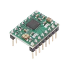
    SILENTSTEPSTICK.png

    SILENTSTEPSTICK.png

    A4988Thumbnail

    TMC2209_STEPPER_MOTOR SILENTSTEPSTICK

    TMC2209_STEPPER_MOTOR SILENTSTEPSTICK thumbnail
    42.3mm NEMA17 Smart Stepper-Motor Module: STM32G0B1, TMC2209 Driver, AS5600 Encoder, CAN Interface, 24V Power Management

    Properties

    Integrated Circuit

    bottom solid GND

    42.3 mm x 42.3 mm square

    mm

    graph LR P24[24V Input] -->|VIN| Buck[MP1584EN Buck Converter] Buck -->|3.3V| V3V3[3.3V Rail] V3V3 --> STM32[STM32G0B1CCT6] V3V3 --> CANPHY[SN65HVD230D CAN PHY] V3V3 --> AS5600[AS5600 Sensor] V3V3 --> TMC[TMC2209-LA Driver] STM32 -->|I2C SDA/SCL| AS5600 STM32 -->|UART Single-Wire| TMC STM32 -->|STEP/DIR/ENABLE/MS| TMC STM32 -->|SWD| SWD[SWD Header] STM32 -->|CAN TX/RX| CANPHY -->|CAN Bus| CANBus[CAN Bus] TMC -->|Motor Phases| Motor[Motor Phases Connector]

    JLC 2-layer 1 oz

    BIGTREETECH

    BIGTREETECH-TMC2209-V1.2

    U

    Pricing & Availability

    Distributor

    Qty 1

    Arrow

    $8.92–$10.83

    Digi-Key

    $15.57–$18.04

    LCSC

    $14.34

    Mouser

    $24.70

    TME

    $11.89

    Verical

    $7.91–$14.90

    Controls