Drone Flight Controller Overview
Thought for NaN days
Project purpose
Clocking and support parts
How the blocks interact
1) Power path
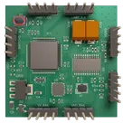
This looks like a drone flight controller reference design built around IC1. The project description and schematic show three main functions combined on one board:
- Flight control and I/O processing by IC1
- 6-axis motion sensing by U5
- Analog video on-screen display insertion by U2
So the board is meant to be the central controller for an FPV-style aircraft: it reads inertial motion data, exposes UART/I2C/switch/LED connections, and overlays telemetry or status graphics onto a composite video feed.
Core components
Main functional blocks
Table
| Block | Main part | What it does |
|---|---|---|
| MCU | IC1 | STM32F405. Its datasheet says it is an Arm Cortex-M4 MCU up to 168 MHz, with USB, SPI, I2C, UARTs, timers, ADCs, and many GPIOs. |
| IMU | U5 | MPU-6000. Its datasheet describes it as a 6-axis MotionTracking device with a 3-axis gyroscope and 3-axis accelerometer, plus SPI/I2C capability. |
| Video OSD | U2 | MAX7456. Its datasheet says it is a single-channel monochrome on-screen display generator for NTSC/PAL composite video, controlled over SPI. |
| 3.3 V regulator | U1 | AMS1117-3.3. Its datasheet says it is a fixed 3.3 V LDO rated up to 800 mA. |
Table
| Function | Parts | Role |
|---|---|---|
| MCU clock | Y1 | 8 MHz Murata ceramic resonator for IC1. |
| OSD clock | X1 | 27 MHz crystal for U2, matching the MAX7456 datasheet requirement for a 27 MHz clock. |
| USB data conditioning | R7, R8 | 22 Ω series resistors on the USB D+/D- lines from USB to IC1. |
| I2C pullups | R2, R5 | 4.7 kΩ pullups to +3V3 for the I2C/UART header. |
| Boot/reset setup | R4, S1 | BOOT0 pull/down-up control and button input for IC1. |
| Status LEDs | LED1, LED2, R16, R17 | Two indicator LEDs driven from IC1 through 1 kΩ resistors. |
- External USB power enters through USB on +V_USB.
- D2 is a BAT54C dual Schottky diode used in the input power path.
- U1 converts the incoming supply to +3V3.
- The +3V3 rail powers IC1 and U5, with local decoupling from C4, C6, C10, C11, C12, and C13.
- The +5V rail is kept for the analog video/OSD section, especially U2, whose datasheet requires AVDD/DVDD/PVDD = 4.75 V to 5.25 V.
This project is a STM32F405-based drone flight controller template where IC1 reads motion data from U5, manages external interfaces, and drives U2 to overlay flight data onto an analog FPV video signal.
If you want, I can next break it down into:
- power architecture
- pin-by-pin interface map for IC1
- likely firmware functions
- potential design issues or review observations
Power architecture review
MCU pin map
BOM sourcing check
Layout planning