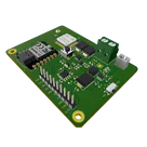
Board Refactor Plan
1:33
Formulating implementation steps.
Linking components and planning.
Clarifying the plan for components.
Executing the plan with knowledge calls.
Accessing knowledge base.
Planning execution steps.
- Remove legacy/THT; keep U4/J2; define VSYS; clear ERC single‑pin nets.
- Add Solar/Batt edge pads; PFET reverse + OVP; LiFePO4 charger 50 mA → VSYS; indicators.
- Add low‑Iq 3.3 V LDO and 5 V boost (30/40 mA) from VSYS with decoupling.
- Add Tag‑Connect TC2030 SWD; 2.54 mm castellated I2C (4.7 k, ≤400 pF), UART (PA2/PA3), two one‑wire (PB13/PB15) with 2‑pad 3.3/5 V jumpers; 3V3/5V/GND pads.
- Square outline, center U4, blue soldermask; preserve RF keepouts; ERC/DRC clean; update BOM/labels.
Started implementing a plan
#Goal
- Refactor The Green Dot 2040E5 board into a LoRa‑E5‑only design by removing legacy/THT power blocks and integrating a new solar LiFePO4 subsystem. The design will include a VSYS rail generated from a PFET reverse‑protected and OVP-enabled solar/LiFePO4 charger (capped at 50 mA), a low‑Iq +3V3 LDO, a 5V boost converter (30 mA cont/40 mA peak), Tag‑Connect TC2030 SWD interface, and SMD 2.54 mm castellated edge pads for I2C (with 4.7 k pull‑ups and ≤400 pF capacitance), UART (PA2/PA3), and two one‑wire interfaces (PB13/PB15) selectable for 3.3 V or 5 V operation. The PCB must remain compact, square, blue in soldermask, with U4 centrally located and RF path preserved (U4:RFIO → J2).
#Implementation plan
1. **Schematic Cleanup and Legacy Removal**
1. Remove legacy/THT power blocks and orphan nets (e.g., J4, J5, U9, U10, IC4) while preserving U4 (LoRa‑E5 module) and J2 (RF connector).
2. Ensure all power pins on ICs are connected to eliminate ERC single‑pin nets.
2. **Solar LiFePO4 Subsystem and VSYS Rail**
1. Add Solar+/Solar− and Batt+/Batt− edge pads for external connections.
2. Integrate a PFET reverse‐protect circuit with overvoltage protection (OVP) for solar input.
3. Implement a LiFePO4 charger instance capped at 50 mA and set up the power‑path, feeding the VSYS rail.
4. Add charge/protect indicator components as needed.
3. **Power Regulation and Rails**
1. Derive a low‑Iq +3V3 rail from the VSYS rail using an appropriate LDO with low dropout suitable for LiFePO4 minimum voltage.
2. Add a boost converter circuit to generate a regulated 5V_OUT rail (30 mA continuous / 40 mA peak) from VSYS, including necessary decoupling capacitors.
4. **Debug and I/O Expansion**
1. Integrate a Tag‑Connect TC2030 footprint for the SWD interface.
2. Create SMD 2.54 mm castellated edge pads for:
1. I2C: include 4.7 k pull‑ups on the I²C lines ensuring bus capacitance ≤400 pF.
2. UART: connect PA2/PA3 from the MCU as required.
3. Two one‑wire interfaces on PB13/PB15 with 2‑pad solder jumpers to select between 3.3 V (default) and 5 V pull‑ups.
3. Preserve the U4:RFIO to J2 connection to maintain RF performance.
4. Add additional 3V3, 5V, and GND pads for ease of testing and debugging.
5. **PCB Layout and Finalization**
1. Configure the PCB layout to be a compact square design with U4 centered and a blue soldermask.
2. Place and route critical RF paths (maintaining 50‑ohm feeds) and ensure keepout areas for RF performance around J2 and U4.
3. Confirm all ERC/DRC errors are resolved; update the BOM with real MPNs and parts data.
#Success criteria
- Achieve a LoRa‑E5‑only board with all legacy power blocks removed and the new solar LiFePO4 charging circuit implemented (50 mA max current).
- Successfully generate a functional VSYS rail that supports both the low‑Iq +3V3 LDO and 5V boost converter.
- Provide complete SMD 2.54 mm castellated edge pads for I2C (with proper pull‑ups), UART, and one‑wire interfaces with selectable voltage options.
- Maintain clean ERC/DRC checks and a compact, centered U4 layout with a blue PCB soldermask.
Working on your request...
51:20
removed legacy power blocks and connectors
0:20
Accessing knowledge base.
Started: removing legacy power blocks and orphan nets
Removed 5 components
0:04
Completed your request.
0:47
Started: reviewing ERC/DRC and fixing orphan nets
Running design review.
Running design review.
Removed 7 components
0:05
0:00
- Removed the legacy/THT power chain components: J4, J5, U9, U10, and IC4.
- Started ERC cleanup by removing a set of now-orphaned single-pin parts: L1, L2, R1, R2, R6, R8, R9.
- Pulled in the required schematic/layout constraint checklists so we keep wiring complete and avoid leaving floating subsystems .
- ✅ Legacy/THT power blocks removed (at least the ones explicitly called out: J4, J5, U9, U10, IC4)
- ❌ ERC is still reporting “Single Pin Nets” for parts that no longer exist (stale ERC list), so we need a fresh schematic snapshot + fresh review readback before proceeding
- ❌ Solar/LiFePO4 charger + VSYS PFET/OVP, +3V3 LDO, 5V boost, castellated edge pads, and one-wire voltage-select jumpers not implemented yet
- I will re-fetch the schematic to confirm the parts are truly gone and identify any remaining orphan nets/portals, then re-run ERC until it is clean (per the “don’t mark complete with wiring/floating issues” rule ).
- After ERC is clean, I’ll add the new power architecture (Solar/Batt edge pads -> PFET reverse protect + OVP -> LiFePO4 charger @ 50 mA max -> VSYS -> +3V3 LDO + 5V boost), and then add I2C pullups (4.7k) and the one-wire jumper-select pullups (3V3 default / 5V option) following the I2C pull-up wiring guidance .
Ready to start.
Show Plan
Reviews

- Wirelessly connects nets on schematic. Used to organize schematics and separate functional blocks. To wirelessly connect net portals, give them same designator. #portaljharwinbarrozo43.0M
- Wirelessly connects power nets on schematic. Identical to the net portal, but with a power symbol. Used to organize schematics and separate functional blocks. To wirelessly connect power net portals, give them the same designator. #portal #powerjharwinbarrozo11.4M
- A generic fixed resistor ideal for rapid circuit topology development. Its footprint automatically adapts based on the selected package case code—supporting 0402, 0603, 0805, 1203, and many other standard SMD packages, as well as axial horizontal and vertical configurations. Save precious design time by seamlessly add more information to this part (value, footprint, etc.) as it becomes available. Standard resistor values: 1.0 ohm, 10 ohm, 100 ohm, 1.0k ohm, 10k ohm, 100k ohm, 1.0M ohm 1.1 ohm, 11 ohm, 110 ohm, 1.1k ohm, 11k ohm, 110k ohm, 1.1M ohm 1.2 ohm, 12 ohm, 120 ohm, 1.2k ohm, 12k ohm, 120k ohm, 1.2M ohm 1.3 ohm, 13 ohm, 130 ohm, 1.3k ohm, 13k ohm, 130k ohm, 1.3M ohm 1.5 ohm, 15 ohm, 150 ohm, 1.5k ohm, 15k ohm, 150k ohm, 1.5M ohm 1.6 ohm, 16 ohm, 160 ohm, 1.6k ohm, 16k ohm, 160k ohm, 1.6M ohm 1.8 ohm, 18 ohm, 180 ohm, 1.8K ohm, 18k ohm, 180k ohm, 1.8M ohm 2.0 ohm, 20 ohm, 200 ohm, 2.0k ohm, 20k ohm, 200k ohm, 2.0M ohm 2.2 ohm, 22 ohm, 220 ohm, 2.2k ohm, 22k ohm, 220k ohm, 2.2M ohm 2.4 ohm, 24 ohm, 240 ohm, 2.4k ohm, 24k ohm, 240k ohm, 2.4M ohm 2.7 ohm, 27 ohm, 270 ohm, 2.7k ohm, 27k ohm, 270k ohm, 2.7M ohm 3.0 ohm, 30 ohm, 300 ohm, 3.0K ohm, 30K ohm, 300K ohm, 3.0M ohm 3.3 ohm, 33 ohm, 330 ohm, 3.3k ohm, 33k ohm, 330k ohm, 3.3M ohm 3.6 ohm, 36 ohm, 360 ohm, 3.6k ohm, 36k ohm, 360k ohm, 3.6M ohm 3.9 ohm, 39 ohm, 390 ohm, 3.9k ohm, 39k ohm, 390k ohm, 3.9M ohm 4.3 ohm, 43 ohm, 430 ohm, 4.3k ohm, 43K ohm, 430K ohm, 4.3M ohm 4.7 ohm, 47 ohm, 470 ohm, 4.7k ohm, 47k ohm, 470k ohm, 4.7M ohm 5.1 ohm, 51 ohm, 510 ohm, 5.1k ohm, 51k ohm, 510k ohm, 5.1M ohm 5.6 ohm, 56 ohm, 560 ohm, 5.6k ohm, 56k ohm, 560k ohm, 5.6M ohm 6.2 ohm, 62 ohm, 620 ohm, 6.2k ohm, 62K ohm, 620K ohm, 6.2M ohm 6.8 ohm, 68 ohm, 680 ohm, 6.8k ohm, 68k ohm, 680k ohm, 6.8M ohm 7.5 ohm, 75 ohm, 750 ohm, 7.5k ohm, 75k ohm, 750k ohm, 7.5M ohm 8.2 ohm, 82 ohm, 820 ohm, 8.2k ohm, 82k ohm, 820k ohm, 8.2M ohm 9.1 ohm, 91 ohm, 910 ohm, 9.1k ohm, 91k ohm, 910k ohm, 9.1M ohm #generics #CommonPartsLibraryjharwinbarrozo1.5M
- A generic fixed capacitor ideal for rapid circuit topology development. You can choose between polarized and non-polarized types, its symbol and the footprint will automatically adapt based on your selection. Supported options include standard SMD sizes for ceramic capacitors (e.g., 0402, 0603, 0805), SMD sizes for aluminum electrolytic capacitors, and through-hole footprints for polarized capacitors. Save precious design time by seamlessly add more information to this part (value, footprint, etc.) as it becomes available. Standard capacitor values: 1.0pF, 10pF, 100pF, 1000pF, 0.01uF, 0.1uF, 1.0uF, 10uF, 100uF, 1000uF, 10000uF 1.1pF, 11pF, 110pF, 1100pF 1.2pF, 12pF, 120pF, 1200pF 1.3pF, 13pF, 130pF, 1300pF 1.5pF, 15pF, 150pF, 1500pF, 0.015uF, 0.15uF, 1.5uF, 15uF, 150uF, 1500uF 1.6pF, 16pF, 160pF, 1600pF 1.8pF, 18pF, 180pF, 1800pF 2.0pF, 20pF, 200pF, 2000pF 2.2pF, 22pF, 220pF, 2200pF, 0.022uF, 0.22uF, 2.2uF, 22uF, 220uF, 2200uF 2.4pF, 24pF, 240pF, 2400pF 2.7pF, 27pF, 270pF, 2700pF 3.0pF, 30pF, 300pF, 3000pF 3.3pF, 33pF, 330pF, 3300pF, 0.033uF, 0.33uF, 3.3uF, 33uF, 330uF, 3300uF 3.6pF, 36pF, 360pF, 3600pF 3.9pF, 39pF, 390pF, 3900pF 4.3pF, 43pF, 430pF, 4300pF 4.7pF, 47pF, 470pF, 4700pF, 0.047uF, 0.47uF, 4.7uF, 47uF, 470uF, 4700uF 5.1pF, 51pF, 510pF, 5100pF 5.6pF, 56pF, 560pF, 5600pF 6.2pF, 62pF, 620pF, 6200pF 6.8pF, 68pF, 680pF, 6800pF, 0.068uF, 0.68uF, 6.8uF, 68uF, 680uF, 6800uF 7.5pF, 75pF, 750pF, 7500pF 8.2pF, 82pF, 820pF, 8200pF 9.1pF, 91pF, 910pF, 9100pF #generics #CommonPartsLibraryjharwinbarrozo1.5M
- A generic fixed inductor suitable for rapid circuit topology development. The footprint automatically adapts based on the selected package, supporting standard SMD sizes (e.g., 0402, 0603, 0805) as well as well-known inductor packages such as SDR1806, PA4320, SRN6028, and SRR1260. Standard inductor values: 1.0 nH, 10 nH, 100 nH, 1.0 µH, 10 µH, 100 µH, 1.0 mH 1.2 nH, 12 nH, 120 nH, 1.2 µH, 12 µH, 120 µH, 1.2 mH 1.5 nH, 15 nH, 150 nH, 1.5 µH, 15 µH, 150 µH, 1.5 mH 1.8 nH, 18 nH, 180 nH, 1.8 µH, 18 µH, 180 µH, 1.8 mH 2.2 nH, 22 nH, 220 nH, 2.2 µH, 22 µH, 220 µH, 2.2 mH 2.7 nH, 27 nH, 270 nH, 2.7 µH, 27 µH, 270 µH, 2.7 mH 3.3 nH, 33 nH, 330 nH, 3.3 µH, 33 µH, 330 µH, 3.3 mH 3.9 nH, 39 nH, 390 nH, 3.9 µH, 39 µH, 390 µH, 3.9 mH 4.7 nH, 47 nH, 470 nH, 4.7 µH, 47 µH, 470 µH, 4.7 mH 5.6 nH, 56 nH, 560 nH, 5.6 µH, 56 µH, 560 µH, 5.6 mH 6.8 nH, 68 nH, 680 nH, 6.8 µH, 68 µH, 680 µH, 6.8 mH 8.2 nH, 82 nH, 820 nH, 8.2 µH, 82 µH, 820 µH, 8.2 mH #generics #CommonPartsLibraryjharwinbarrozo15.7k
- An electrical connector acting as reusable interface to a conductor and creating a point where external circuits can be connected.Terminal
- 47 kOhms ±5% 0.125W, 1/8W Chip Resistor 0805 (2012 Metric) Automotive AEC-Q200 Thick Film #forLedBlinkjharwinbarrozo1.2M
- 10uF Capacitor Aluminum Polymer 20% 16V SMD 5x5.3mm #forLedBlink #commonpartslibrary #capacitor #aluminumpolymer #radialcanjharwinbarrozo1.2M
- Yellow 595nm LED Indication - Discrete 1.7V 1206 (3216 Metric) #forLedBlinkjharwinbarrozo1.1M


Properties
Properties describe core aspects of the project.
Pricing & Availability
Distributor | Qty 1 |
|---|---|
Arrow | $13.98–$18.87 |
Digi-Key | $11.61–$14.77 |
LCSC | $12.72 |
Mouser | $18.56 |
TME | $0.80 |
Verical | $2.88–$10.77 |
Controls
Welcome 👋
Flux helps you build PCBs faster with an AI teammate!
Create your account to collaborate, stay updated, fork your own version, and get instant answers from our AI agent.