Chat
Welcome to Flux
Treat Flux like your intern. Tell it what you'd like to build and it'll get to work. You can also ask it questions, brainstorm ideas, and teach it your preferences. Learn More
Explain project
Write a project description
Find schematic issues
Create a test plan
Simulate a circuit
Prepare for Manufacturing
Component Selection Workflow
New Subsystem Wizard
Write I2C initialization code
Generate firmware skeleton
U8
what is the purpose of U2 in the circuit

2y
The U2 component in this project is a CN3063 chip, a linear single cell Li-Ion battery charger. This device is important in managing the charging of a Li-Ion battery from a solar panel (or any DC source). It controls the battery charging process to ensure safe charging and optimizes the battery life and performance. It also includes some safety features such as preventing overcharging and overcurrent.
In this context, it assumes that there's a solar panel and a battery involved in your project. I'm making this assumption based on the typical use-case of CN3063 and the mention of the "VSOLAR" net.
Please correct me if my assumption is wrong. Also, note that U2 should have been specified with a list of pins which are assumed connected in this response.
2y
Someone is typing...
3
\[librarian] is L2 the right size for U1?
2y
To determine if L2 (an inductor with a value of 2.2uH from the manufacturer Sunlord, part number SWPA3015S2R2MT) is appropriately sized for U1 (an RT8059GJ5 which I'm assuming is a DC/DC converter), we'd ideally consult the datasheets for both parts. However, I'm sorry, but unfortunately we don't have datasheet excerpts for either of these components available.
Usually, the datasheet of a DC-DC converter like U1 provides guidance on the suitable inductance value and sometimes even particular models of inductors that work well. The datasheet might specify minimum and maximum inductance, rated current, saturation current, and other essential parameters.
Given the regular operation of DC/DC converters, a 2.2µH inductor could be a reasonable choice, but without the datasheets or a design guide from the manufacturer, it's hard to confirm for sure. You should look up the datasheets or any application notes for the two components yourself to ensure compatibility.
Please note that the values I'm giving are purely assumptions based on general electrical engineering practices, as we don't have the datasheets or exact values provided. If these assumptions are invalid for your specific use case, you may need to provide more information.
2y
Someone is typing...
1
+3V3
+3V3
+3V3
VSOLAR
VBAT
VBAT
+3V3
VBAT
+3V3
12_5V
VBAT
VSOLAR
VUSB
+3V3
J3
C11
Capacitance
4u7 F
U6
C1
Capacitance
10uF
VUSB
A
PIO2
SDA
PIO2
A
C4
Capacitance
4u7 F
SCL
+3V3
C2
Capacitance
10uF
C3
Capacitance
100nF
C8
Not Recommended for New Designs
Capacitance
68pF
+3V3
RX
NRST
RO
B
B
RX
NRST
TX
SDA
C10
Capacitance
22uF
PIO1
DI
C9
Capacitance
100nF
ENABLE
SCL
TX
C12
Capacitance
100nF
C7
Capacitance
22uF
PIO1
DI
12_5V
C6
Capacitance
100nF
C5
Capacitance
10uF
RO
R15
Resistance
4k7 Ω
R9
Resistance
20kΩ
R16
Resistance
4k7 Ω
R11
Resistance
22 Ω
R14
Resistance
120 Ω
R8
Resistance
2kΩ
R7
Resistance
15kΩ
R6
Resistance
150kΩ
R1
Resistance
3kΩ
R2
Resistance
1k5 Ω
R17
Resistance
4k7 Ω
R10
Resistance
22 Ω
R4
Resistance
4k7
Ω
R13
Resistance
470 Ω
R3
Resistance
68kΩ
R5
Resistance
6k8 Ω
R18
Resistance
22 Ω
U3
U1
IC1
L1
Inductance
10uH
SW2
U4
L2
Inductance
2u2 H
D1
IC2
J1
U5
D4
D5
Color
Red
U7
SW1
D2
Color
Green
D3
J6
H2
H1
U2
J2
No files yet
Reviews
Documents
Documents are markdown text files which describe project goals, capture details, or even simulation outputs.
Assets
svg
flux logo.svg
flux logoDefault
image-removebg.png
image-removebgThumbnailThe Green Dot 2040E5 Board w8QA
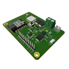
The "Green Dot 2040E5" Board is a Node that interfaces RS485 Sensor probes and can log information to the cloud using LoRa Connectivity. It uses the XIAO RP2040 and the LoRa-E5 (STM32WLE5JC) modules from Seeed Studio to do its magic. It also has amazing power management capabilities (Solar charging, Battery protection, etc) that make it very useful for IoT applications
#Seeed #XIOA #LoRa #RP2040 #IoT
Properties
Properties describe core aspects of the project.
Pricing & Availability
Distributor | Qty 1 |
|---|---|
Digi-Key | $16.01–$17.09 |
LCSC | $1.89–$3.07 |
Mouser | $19.37–$19.91 |
Controls
Welcome 👋
Flux helps you build PCBs faster with an AI teammate!
Create your account to collaborate, stay updated, fork your own version, and get instant answers from our AI agent.
L_Sunlord_SWPA4030S
L_Sunlord_SWPA3015S
kerry
copilot