Adding Right-Angle Header Connector


You can’t add it directly to this project because you don’t have edit access here.
A good next step is to fork this project and add the connector there. Here’s a ready-to-use fork link:
If you want, I can also help you narrow it to a specific right-angle header connector before you fork.
Find a 2.54mm pitch right-angle 8x3 through-hole female header in the library.
I couldn’t find an exact 2.54 mm, right-angle, through-hole, female, 8 x 3 header in the Flux library.
Closest library matches:
  • 61301221021 - through-hole, right-angle, 12-position, 2.54 mm pitch. Closest mechanical style, but not 8 x 3 or 24-position.
  • 610112249221 - right-angle, 12-position, 2.54 mm pitch, but SMD, not through-hole.
  • 3020-10-0300-00 - 10-position, 2.54 mm pitch, but not the requested arrangement.
Best practical fallback:
  • Use two of 61301221021 if a split 24-position solution is acceptable.
I also submitted a missing-part request for an exact right-angle female 24-position / 8 x 3 or 2 x 12 header.
If you want, I can next:
  • search for a specific manufacturer MPN to request/add, or
  • find the best male/right-angle 8 x 3 alternative already in the library.
Search by MPN
Find male alternative
Check other row counts

2
MAKE ARDUINO NANO CONNECT

@copilot MAKE ARDUINO NANO CONNECT
2y
In order to make your project using the Arduino Nano RP2040 Connect, you will need to connect the pins of your Arduino to the required components of your project. Since there aren't any specific peripheral components listed in your project, I'm going to assume that you want to know how to connect some general components like LEDs, buttons and sensors to the Arduino.
Here are some general guidelines:
  1. For LEDs:
    • Connect the cathode (shorter lead) of the LED to a current-limiting resistor (220-1K ohm typically).
    • Connect the other terminal of the resistor to the digital I/O pin of the Arduino that you want to control the LED with (e.g., D13/GPIO6).
    • Connect the anode (longer lead) of the LED to Ground (GND__1 or GND).
  2. For Buttons:
    • Connect one side of the button to a digital I/O pin (e.g., D10/GPIO5).
    • Connect the other side of the button to Ground (GND__1 or GND).
    • To avoid "floating states" (undefined states) when the button is not pressed, use an internal or external pull-up resistor connected to +3V3 or +5V.
  3. For Analog Sensors:
    • Connect the Vcc (power) pin of the sensor to +3V3 or +5V depending on the requirements of the sensor.
    • Connect the GND pin of the sensor to Ground (GND__1 or GND).
    • Connect the Analog output of the sensor to one of the Analog Input pins (e.g., A0/DAC0/GPIO26, A1/GPIO27, A2/GPIO28, A3/GPIO29, A4/GPIO12, A5/GPIO13, A6, or A7).
NOTE: Always refer to the datasheet of the component/sensor you're using. The voltage levels (+3V3 or +5V) should match the operating voltage level of the sensor.
Once you've made the physical connections, you can program the Arduino Nano RP2040 Connect using the Arduino IDE.
Please provide more specific details if you need help connecting specific components to your Arduino.
2y
Hello 👋
1y
Hello! 👋 How can I assist you today with your Arduino Nano RP2040 Connect project or any other electronics design questions you might have?
1y
1y
It looks like you're mentioning the 5V power supply. How can I help you with that? Are you looking to power the Arduino Nano RP2040 Connect, or do you need advice on connecting a component that requires 5V? Let me know how I can assist you further!
1y
Someone is typing...
Name
Pin #
Type
Part Type
Terminal Order
Terminal Type
D13/GPIO6
1
Unspecified
Terminal
bidi
+3V3
2
Unspecified
Terminal
powerIn
AREF
3
Unspecified
Terminal
bidi
A0/DAC0/GPIO26
4
Unspecified
Terminal
bidi
A1/GPIO27
5
Unspecified
Terminal
bidi
A2/GPIO28
6
Unspecified
Terminal
bidi
A3/GPIO29
7
Unspecified
Terminal
bidi
A4/GPIO12
8
Unspecified
Terminal
bidi
A5/GPIO13
9
Unspecified
Terminal
bidi
A6
10
Unspecified
Terminal
bidi
A7
11
Unspecified
Terminal
bidi
+5V
12
Unspecified
Terminal
powerIn
QSPI_~RESET
13
Unspecified
Terminal
INPUT
GND
14
Unspecified
Terminal
powerIn
VIN
15
Unspecified
Terminal
powerIn
TX
16
Unspecified
Terminal
bidi
RX
17
Unspecified
Terminal
bidi
~RESET
18
Unspecified
Terminal
INPUT
GND__1
19
Unspecified
Terminal
powerIn
D2/GPIO25
20
Unspecified
Terminal
bidi
D3/GPIO15
21
Unspecified
Terminal
bidi
D4/GPIO26
22
Unspecified
Terminal
bidi
D5/GPIO17
23
Unspecified
Terminal
bidi

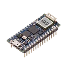
Arduino Nano RP2040 Connect with headers