Schematic Component Review

Here’s a compact in-line car-audio bass level controller with an integrated voltmeter and remote turn-on control, optimized for low-noise passive audio and robust 12 V automotive power.
Block diagram

Diagram


Car node_12V input PTC polyfuse Reverse polarity SS34 or P-MOSFET "TVS diode (58V class)" 5V LDO MCU with ADC TM1637 4-digit LED display Remote IN node_12V High-side P-MOSFET "Pot integrated switch (SPST)" Remote OUT node_12V RCA IN L/R Dual-gang node_50k log attenuator RCA OUT L/R
Recommended components from the library
Audio path
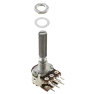
  • Dual-gang 50k audio taper potentiometer:
    • PDB182-K430K-503A (Bourns, 50k log, dual gang). Note: verify/choose the variant with integrated SPST “click” switch for the remote control requirement; if not available, pick the switch-equipped version in the PDB18 family.
  • RCA jacks (4x, female, board mount):
Power input and protection
Remote turn-on switching
  • High-side PFET (12 V signal line):
Controller and display
Voltage sensing and decoupling passives
Design notes (applied best practices)
  • Grounding for low noise: prioritize ground separation (audio return vs. digital/display return) because return paths dominate noise coupling. Tie at a single star near the power entry or RCA ground reference.
  • ADC divider drive: check divider output impedance using (R1*R2)/(R1+R2). If it exceeds the MCU ADC input spec, buffer or lower the divider values.
  • Regulator sizing: ensure the 5 V regulator supports total load current with a 25% buffer, and operate power ICs at no more than 75% of their rated maximum power.
  • Supply bypassing: switching/display noise issues are often fixed by proper bypassing first; place 100 nF at each IC VCC pin and keep traces short.
  • Audio THD: keep the audio path passive (dual 50k log pot between RCA IN/OUT), route audio away from the digital display and 12 V rails, and use a star ground at the RCA shield.
Clarify before we implement
  • Potentiometer with switch: OK to use the Bourns PDB18 family and select the variant with integrated SPST “click” switch? If you prefer Alpha/WH148 style, I can swap to that family.
  • Display choice: keep the TM1637 module for speed, or switch to a discrete LED + driver for a slimmer board?
  • Headers: confirm pin order for JST-XH 3-pin remote header (e.g., 1=REM_IN, 2=GND, 3=REM_OUT).
Confirm pot with switch
Choose display style
Ask for divider calculation
Grounding/layout guidance
Remote header pinout
R1_WIPER
R1_CW
R1_CCW
R2_CW
R2_COM
R2_CCW


  • Generic Inductor
    A generic fixed inductor suitable for rapid circuit topology development. The footprint automatically adapts based on the selected package, supporting standard SMD sizes (e.g., 0402, 0603, 0805) as well as well-known inductor packages such as SDR1806, PA4320, SRN6028, and SRR1260. Standard inductor values: 1.0 nH, 10 nH, 100 nH, 1.0 µH, 10 µH, 100 µH, 1.0 mH 1.2 nH, 12 nH, 120 nH, 1.2 µH, 12 µH, 120 µH, 1.2 mH 1.5 nH, 15 nH, 150 nH, 1.5 µH, 15 µH, 150 µH, 1.5 mH 1.8 nH, 18 nH, 180 nH, 1.8 µH, 18 µH, 180 µH, 1.8 mH 2.2 nH, 22 nH, 220 nH, 2.2 µH, 22 µH, 220 µH, 2.2 mH 2.7 nH, 27 nH, 270 nH, 2.7 µH, 27 µH, 270 µH, 2.7 mH 3.3 nH, 33 nH, 330 nH, 3.3 µH, 33 µH, 330 µH, 3.3 mH 3.9 nH, 39 nH, 390 nH, 3.9 µH, 39 µH, 390 µH, 3.9 mH 4.7 nH, 47 nH, 470 nH, 4.7 µH, 47 µH, 470 µH, 4.7 mH 5.6 nH, 56 nH, 560 nH, 5.6 µH, 56 µH, 560 µH, 5.6 mH 6.8 nH, 68 nH, 680 nH, 6.8 µH, 68 µH, 680 µH, 6.8 mH 8.2 nH, 82 nH, 820 nH, 8.2 µH, 82 µH, 820 µH, 8.2 mH #generics #CommonPartsLibrary
  • Generic Capacitor
    A generic fixed capacitor ideal for rapid circuit topology development. You can choose between polarized and non-polarized types, its symbol and the footprint will automatically adapt based on your selection. Supported options include standard SMD sizes for ceramic capacitors (e.g., 0402, 0603, 0805), SMD sizes for aluminum electrolytic capacitors, and through-hole footprints for polarized capacitors. Save precious design time by seamlessly add more information to this part (value, footprint, etc.) as it becomes available. Standard capacitor values: 1.0pF, 10pF, 100pF, 1000pF, 0.01uF, 0.1uF, 1.0uF, 10uF, 100uF, 1000uF, 10000uF 1.1pF, 11pF, 110pF, 1100pF 1.2pF, 12pF, 120pF, 1200pF 1.3pF, 13pF, 130pF, 1300pF 1.5pF, 15pF, 150pF, 1500pF, 0.015uF, 0.15uF, 1.5uF, 15uF, 150uF, 1500uF 1.6pF, 16pF, 160pF, 1600pF 1.8pF, 18pF, 180pF, 1800pF 2.0pF, 20pF, 200pF, 2000pF 2.2pF, 22pF, 220pF, 2200pF, 0.022uF, 0.22uF, 2.2uF, 22uF, 220uF, 2200uF 2.4pF, 24pF, 240pF, 2400pF 2.7pF, 27pF, 270pF, 2700pF 3.0pF, 30pF, 300pF, 3000pF 3.3pF, 33pF, 330pF, 3300pF, 0.033uF, 0.33uF, 3.3uF, 33uF, 330uF, 3300uF 3.6pF, 36pF, 360pF, 3600pF 3.9pF, 39pF, 390pF, 3900pF 4.3pF, 43pF, 430pF, 4300pF 4.7pF, 47pF, 470pF, 4700pF, 0.047uF, 0.47uF, 4.7uF, 47uF, 470uF, 4700uF 5.1pF, 51pF, 510pF, 5100pF 5.6pF, 56pF, 560pF, 5600pF 6.2pF, 62pF, 620pF, 6200pF 6.8pF, 68pF, 680pF, 6800pF, 0.068uF, 0.68uF, 6.8uF, 68uF, 680uF, 6800uF 7.5pF, 75pF, 750pF, 7500pF 8.2pF, 82pF, 820pF, 8200pF 9.1pF, 91pF, 910pF, 9100pF #generics #CommonPartsLibrary
  • Generic Resistor
    A generic fixed resistor ideal for rapid circuit topology development. Its footprint automatically adapts based on the selected package case code—supporting 0402, 0603, 0805, 1203, and many other standard SMD packages, as well as axial horizontal and vertical configurations. Save precious design time by seamlessly add more information to this part (value, footprint, etc.) as it becomes available. Standard resistor values: 1.0 ohm, 10 ohm, 100 ohm, 1.0k ohm, 10k ohm, 100k ohm, 1.0M ohm 1.1 ohm, 11 ohm, 110 ohm, 1.1k ohm, 11k ohm, 110k ohm, 1.1M ohm 1.2 ohm, 12 ohm, 120 ohm, 1.2k ohm, 12k ohm, 120k ohm, 1.2M ohm 1.3 ohm, 13 ohm, 130 ohm, 1.3k ohm, 13k ohm, 130k ohm, 1.3M ohm 1.5 ohm, 15 ohm, 150 ohm, 1.5k ohm, 15k ohm, 150k ohm, 1.5M ohm 1.6 ohm, 16 ohm, 160 ohm, 1.6k ohm, 16k ohm, 160k ohm, 1.6M ohm 1.8 ohm, 18 ohm, 180 ohm, 1.8K ohm, 18k ohm, 180k ohm, 1.8M ohm 2.0 ohm, 20 ohm, 200 ohm, 2.0k ohm, 20k ohm, 200k ohm, 2.0M ohm 2.2 ohm, 22 ohm, 220 ohm, 2.2k ohm, 22k ohm, 220k ohm, 2.2M ohm 2.4 ohm, 24 ohm, 240 ohm, 2.4k ohm, 24k ohm, 240k ohm, 2.4M ohm 2.7 ohm, 27 ohm, 270 ohm, 2.7k ohm, 27k ohm, 270k ohm, 2.7M ohm 3.0 ohm, 30 ohm, 300 ohm, 3.0K ohm, 30K ohm, 300K ohm, 3.0M ohm 3.3 ohm, 33 ohm, 330 ohm, 3.3k ohm, 33k ohm, 330k ohm, 3.3M ohm 3.6 ohm, 36 ohm, 360 ohm, 3.6k ohm, 36k ohm, 360k ohm, 3.6M ohm 3.9 ohm, 39 ohm, 390 ohm, 3.9k ohm, 39k ohm, 390k ohm, 3.9M ohm 4.3 ohm, 43 ohm, 430 ohm, 4.3k ohm, 43K ohm, 430K ohm, 4.3M ohm 4.7 ohm, 47 ohm, 470 ohm, 4.7k ohm, 47k ohm, 470k ohm, 4.7M ohm 5.1 ohm, 51 ohm, 510 ohm, 5.1k ohm, 51k ohm, 510k ohm, 5.1M ohm 5.6 ohm, 56 ohm, 560 ohm, 5.6k ohm, 56k ohm, 560k ohm, 5.6M ohm 6.2 ohm, 62 ohm, 620 ohm, 6.2k ohm, 62K ohm, 620K ohm, 6.2M ohm 6.8 ohm, 68 ohm, 680 ohm, 6.8k ohm, 68k ohm, 680k ohm, 6.8M ohm 7.5 ohm, 75 ohm, 750 ohm, 7.5k ohm, 75k ohm, 750k ohm, 7.5M ohm 8.2 ohm, 82 ohm, 820 ohm, 8.2k ohm, 82k ohm, 820k ohm, 8.2M ohm 9.1 ohm, 91 ohm, 910 ohm, 9.1k ohm, 91k ohm, 910k ohm, 9.1M ohm #generics #CommonPartsLibrary
  • Ground
    A common return path for electric current. Commonly known as ground.
  • Terminal
    Terminal
    An electrical connector acting as reusable interface to a conductor and creating a point where external circuits can be connected.
  • Net Portal
    Wirelessly connects nets on schematic. Used to organize schematics and separate functional blocks. To wirelessly connect net portals, give them same designator. #portal
  • RMCF0805JT47K0
    General Purpose Thick Film Standard Power and High-Power Chip Resistor 47 kOhms ±5% 0.125W, 1/8W Chip Resistor 0805 (2012 Metric) Automotive AEC-Q200 Thick Film Features: - RMCF – standard power ratings - RMCP – high power ratings - Nickel barrier terminations standard - Power derating from 100% at 70ºC to zero at +155ºC - RoHS compliant, REACH compliant, and halogen free - AEC-Q200 compliant
  • 875105359001
    10 µF 16 V Aluminum - Polymer Capacitors Radial, Can - SMD 30mOhm 2000 Hrs @ 105°C #commonpartslibrary #capacitor #aluminumpolymer #radialcan
  • CTL1206FYW1T
    Yellow 595nm LED Indication - Discrete 1.7V 1206 (3216 Metric)
  • 1070TR
    Battery Holder (Open) Coin, 20.0mm 1 Cell SMD (SMT) Tab bate or batt #forLedBlink

PDB182-K230K-104A

PDB182-K230K-104A thumbnail
Stereo Active Baxandall Bass Shelf EQ using NE5532 Op-Amp and Bourns PDB182-K230K-104A Dual-Gang Potentiometer

Properties

graph LR subgraph Power Rails VCC --> C_dec_pos[0.1uF Decoupling] -VCC --> C_dec_neg[0.1uF Decoupling] C_dec_pos --> U1.+VCC C_dec_neg --> U1.-VCC GND --> U1.GND end IN_L --> C_in_L[Input Coupling Cap] IN_R --> C_in_R[Input Coupling Cap] C_in_L --> RC_L[Left RC Network] C_in_R --> RC_R[Right RC Network] subgraph Pot R1_CCW & R1_WIPER & R1_CW & R2_CCW & R2_COM & R2_CW end RC_L --> U1.+1IN RC_R --> U1.+2IN U1.1OUT --> C_out_L[Output Coupling Cap] --> OUT_L U1.2OUT --> C_out_R[Output Coupling Cap] --> OUT_R Pot -- controls --> RC_L Pot -- controls --> RC_R

Variable Resistor

Potentiometer (Bourns PDB182 dual-gang) must be placed at the board edge so the shaft exits perpendicular to the front panel. NE5532 supply decoupling capacitors (C1/C2 for +VCC, C9 and local -VCC decouplers) should be placed as close as possible to U1 power pins (+VCC, -VCC) with short, wide traces to the power and ground nets. Input/output audio jacks or headers (IN_L/IN_R/OUT_L/OUT_R) must be placed so connectors are accessible from the panel/edge and spaced sufficiently to avoid mechanical interference between plug bodies.

Consumer Electronics

Switches

Bourns Inc.

PDB182-K230K-104A

VR

Pricing & Availability

Distributor

Qty 1

Arrow

$0.29–$0.36

Digi-Key

$0.36–$1.10

LCSC

$0.23

Mouser

$0.86

TME

$0.78

Verical

$0.20–$0.36

Controls