Chat
Welcome to Flux
Treat Flux like your intern. Tell it what you'd like to build and it'll get to work. You can also ask it questions, brainstorm ideas, and teach it your preferences. Learn More
Explain project
Write a project description
Find schematic issues
Create a test plan
Simulate a circuit
Prepare for Manufacturing
Component Selection Workflow
New Subsystem Wizard
Operating conditions
Part Specifications
Verify Part Details
Recommend similar parts
Ready.
how do I use Flux?
1y
Flux is a comprehensive and user-friendly tool for designing electronic schematics and laying out PCBs. Here are some steps to get you started:
1. Creating an Account
First, create an account on Flux. Visit Flux Signup Page and follow the instructions to sign up with your email, username, and password. You can also link your Google account for quick sign-up[1].
2. Exploring the Interface
Once you log in, you will see the Flux interface, which includes:
- Toolbar: Contains options to add components, routes, and perform other actions.
- Canvas: The workspace where you design your schematic and PCB.
- Component Library: A searchable database of components you can use in your design.
- Inspector: Shows properties and settings for selected components or nets.
To create a schematic:
- Add Components: Drag components from the component library onto the canvas. You can search for specific components by their part number or description.
- Connect Components: Use wires to connect pins of different components. For example, to connect a resistor to a capacitor, you would create a wire connecting the appropriate pins.
Position your components logically and route the connections between them. This step is crucial for PCB design:
- Position Components: Place your components on the canvas in a layout that makes logical sense.
- Route Traces: Connect the components with traces. Ensure that you follow good routing practices, such as avoiding right-angle traces and ensuring clearance between different nets[2].
You can simulate your circuit in Flux to verify its behavior before manufacturing:
- Add Simulation Models: Make sure each component has an associated simulation model.
- Run Simulations: Use the simulator to check for expected performance and identify potential issues[3].
Once your design is complete, you can export it for manufacturing:
- Generate Gerber Files: These files are used by PCB manufacturers to produce your board.
- Export BOM: Generate a Bill of Materials for ordering parts.
If you run into any issues, Flux offers several resources to help you:
- Documentation: Detailed guides on using different features of Flux.
- Community: Join the Slack community where you can ask questions and get answers from other users and the Flux team[4].
- YouTube Tutorials: Explore video tutorials and recorded events for a more visual guide[5].
Would you like more details on any specific part of the process?
1y
Someone is typing...
3
A
K
Reviews

- Wirelessly connects nets on schematic. Used to organize schematics and separate functional blocks. To wirelessly connect net portals, give them same designator. #portaljharwinbarrozo43.0M
- Wirelessly connects power nets on schematic. Identical to the net portal, but with a power symbol. Used to organize schematics and separate functional blocks. To wirelessly connect power net portals, give them the same designator. #portal #powerjharwinbarrozo11.4M
- A generic fixed resistor for rapid developing circuit topology. Save precious design time by seamlessly add more information to this part (value, footprint, etc.) as it becomes available. Standard resistor values: 1.0Ω 10Ω 100Ω 1.0kΩ 10kΩ 100kΩ 1.0MΩ 1.1Ω 11Ω 110Ω 1.1kΩ 11kΩ 110kΩ 1.1MΩ 1.2Ω 12Ω 120Ω 1.2kΩ 12kΩ 120kΩ 1.2MΩ 1.3Ω 13Ω 130Ω 1.3kΩ 13kΩ 130kΩ 1.3MΩ 1.5Ω 15Ω 150Ω 1.5kΩ 15kΩ 150kΩ 1.5MΩ 1.6Ω 16Ω 160Ω 1.6kΩ 16kΩ 160kΩ 1.6MΩ 1.8Ω 18Ω 180Ω 1.8KΩ 18kΩ 180kΩ 1.8MΩ 2.0Ω 20Ω 200Ω 2.0kΩ 20kΩ 200kΩ 2.0MΩ 2.2Ω 22Ω 220Ω 2.2kΩ 22kΩ 220kΩ 2.2MΩ 2.4Ω 24Ω 240Ω 2.4kΩ 24kΩ 240kΩ 2.4MΩ 2.7Ω 27Ω 270Ω 2.7kΩ 27kΩ 270kΩ 2.7MΩ 3.0Ω 30Ω 300Ω 3.0KΩ 30KΩ 300KΩ 3.0MΩ 3.3Ω 33Ω 330Ω 3.3kΩ 33kΩ 330kΩ 3.3MΩ 3.6Ω 36Ω 360Ω 3.6kΩ 36kΩ 360kΩ 3.6MΩ 3.9Ω 39Ω 390Ω 3.9kΩ 39kΩ 390kΩ 3.9MΩ 4.3Ω 43Ω 430Ω 4.3kΩ 43KΩ 430KΩ 4.3MΩ 4.7Ω 47Ω 470Ω 4.7kΩ 47kΩ 470kΩ 4.7MΩ 5.1Ω 51Ω 510Ω 5.1kΩ 51kΩ 510kΩ 5.1MΩ 5.6Ω 56Ω 560Ω 5.6kΩ 56kΩ 560kΩ 5.6MΩ 6.2Ω 62Ω 620Ω 6.2kΩ 62KΩ 620KΩ 6.2MΩ 6.8Ω 68Ω 680Ω 6.8kΩ 68kΩ 680kΩ 6.8MΩ 7.5Ω 75Ω 750Ω 7.5kΩ 75kΩ 750kΩ 7.5MΩ 8.2Ω 82Ω 820Ω 8.2kΩ 82kΩ 820kΩ 8.2MΩ 9.1Ω 91Ω 910Ω 9.1kΩ 91kΩ 910kΩ 9.1MΩ #generics #CommonPartsLibraryjharwinbarrozo1.5M
- A generic fixed capacitor ideal for rapid circuit topology development. You can choose between polarized and non-polarized types, its symbol and the footprint will automatically adapt based on your selection. Supported options include standard SMD sizes for ceramic capacitors (e.g., 0402, 0603, 0805), SMD sizes for aluminum electrolytic capacitors, and through-hole footprints for polarized capacitors. Save precious design time by seamlessly add more information to this part (value, footprint, etc.) as it becomes available. Standard capacitor values: 1.0pF 10pF 100pF 1000pF 0.01uF 0.1uF 1.0uF 10uF 100uF 1000uF 10,000uF 1.1pF 11pF 110pF 1100pF 1.2pF 12pF 120pF 1200pF 1.3pF 13pF 130pF 1300pF 1.5pF 15pF 150pF 1500pF 0.015uF 0.15uF 1.5uF 15uF 150uF 1500uF 1.6pF 16pF 160pF 1600pF 1.8pF 18pF 180pF 1800pF 2.0pF 20pF 200pF 2000pF 2.2pF 22pF 20pF 2200pF 0.022uF 0.22uF 2.2uF 22uF 220uF 2200uF 2.4pF 24pF 240pF 2400pF 2.7pF 27pF 270pF 2700pF 3.0pF 30pF 300pF 3000pF 3.3pF 33pF 330pF 3300pF 0.033uF 0.33uF 3.3uF 33uF 330uF 3300uF 3.6pF 36pF 360pF 3600pF 3.9pF 39pF 390pF 3900pF 4.3pF 43pF 430pF 4300pF 4.7pF 47pF 470pF 4700pF 0.047uF 0.47uF 4.7uF 47uF 470uF 4700uF 5.1pF 51pF 510pF 5100pF 5.6pF 56pF 560pF 5600pF 6.2pF 62pF 620pF 6200pF 6.8pF 68pF 680pF 6800pF 0.068uF 0.68uF 6.8uF 68uF 680uF 6800uF 7.5pF 75pF 750pF 7500pF 8.2pF 82pF 820pF 8200pF 9.1pF 91pF 910pF 9100pF #generics #CommonPartsLibraryjharwinbarrozo1.5M
- A generic fixed inductor for rapid developing circuit topology. *You can now change the footprint and 3D model at the top level anytime you want. This is the power of #genericsjharwinbarrozo15.4k
- An electrical connector acting as reusable interface to a conductor and creating a point where external circuits can be connected.Terminal
- 47 kOhms ±5% 0.125W, 1/8W Chip Resistor 0805 (2012 Metric) Automotive AEC-Q200 Thick Film #forLedBlinkjharwinbarrozo1.2M
- 10uF Capacitor Aluminum Polymer 20% 16V SMD 5x5.3mm #forLedBlink #commonpartslibrary #capacitor #aluminumpolymer #radialcanjharwinbarrozo1.2M
- Yellow 595nm LED Indication - Discrete 1.7V 1206 (3216 Metric) #forLedBlinkjharwinbarrozo1.1M


Inspect
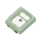
LED 1113 (2835 Metric)
Controls
Properties
Forward Voltage
Part Type
LED
Manufacturer Part Number
Manufacturer Name
Datasheet URL
Designator Prefix
LED
Availability & Pricing
| Distributor | Qty 1 | |
|---|---|---|
Assets
 led-off.svg
id=led-off
 led-on.svg
id=led-on
- LED 1113 (2835 Metric).png
id=LED 1113 (2835 Metric)
- QBHP686.step
id=3D_QBHP686
Default
Thumbnail

3d Model
Welcome 👋
Flux accelerates your PCB design with AI.
Create your account to start using this component and bring your ideas to life.
jdorfman
copilot
-
Select SMD LEDs:
- Ensure the SMD LED type you choose is 1113 (2835 Metric) as you specified earlier.
- Verify the forward voltage and current ratings for proper design, though typical values might be 2.0V to 3.5V depending on the LED color.
-
Create LED Matrix Layout:
- Position the SMD LEDs on your PCB to spell out "Bill".
- You can manually place the LEDs or use a grid placement strategy.
-
Connect LEDs in Series or Parallel with Current-Limiting Resistors:
- Determine if you’ll connect the LEDs in series, parallel, or a combination.
- Each LED might need a current-limiting resistor.
-
Schematic Design:
- Assign designators to each LED.
- Draw connections and add resistors, power supply, and ground.
-
PCB Layout:
- Place the LEDs on the PCB.
- Route the traces to connect the components as per the schematic.
Step-by-Step Instructions Schematic- Top segment: $LED_1$ to $LED_2$
- Vertical segment: $LED_3$ to $LED_4$, $LED_5$
PCB Layout- Place LEDs:
- Position LEDs on the PCB to form the letters "B", "i", "l", "l".
- Route Traces:
- Connect LED anodes to a common VCC plane or rail.
- Each LED cathode connects through a resistor to a ground plane or rail.
Example Project Components- LED:
- $LED_1$, $LED_2$, ..., etc.
- Resistors:
- $R_1$, $R_2$, ..., etc.
- Assume resistor values typically of $330 \Omega$ to $1 k\Omega$.
Connections Examplejdorfman
copilot
-
Schematics:
- Sketch out the arrangement of LEDs and resistors.
- Ensure each letter is correctly formed with enough spacing.
-
Assumptions:
- We’ll assume each segment of a letter is formed by 2-3 LEDs.
- Resistors are placed in series with each LED to limit current.
-
Connections:
Connections Summary- Vertical Bar: $LED_1$ to $LED_5$
- Upper Horizontal Bar: $LED_6$, $LED_7$
- Middle Horizontal Bar: $LED_8$, $LED_9$
- Bottom Horizontal Bar: $LED_{10}$, $LED_{11}$
Sample Visual Placement Schematics Connections-
Vertical Bar:
- Connect:
- $LED_1$: Anode to VCC
- $LED_1$: Cathode to $R_1$: 1; $R_1$: 2 to ground
- Repeat for $LED_2$ to $LED_5$
-
Horizontal Bars:
- Connect:
- $LED_6$: Anode to VCC
- $LED_6$: Cathode to $R_6$: 1; $R_6$: 2 to ground
- Repeat for $LED_7$ to $LED_{11}$
Project Implementation in Flux Step 1: Establish Component and Setup-
Place LEDs:
- Use LED designator: LED1, LED2, etc.
-
Place Resistors:
- Use resistor designator: R1, R2, etc.
Step 2: Connect LEDs to Resistorsjdorfman
copilot
- Create a new project.
- Add components:
- Add SMD LED 1113 (2835 Metric) for each section of the letters.
- Add appropriate resistors (start with 330 $\Omega$) in series with each LED.
Step 2: Placing LEDs for Each Letter-
Vertical Bar of 'B':
- Place 5 LEDs vertically.
- Starting with the top, number them as (LED1), (LED2), ..., (LED5).
- Ensure equal spacing between LEDs for coherence.
-
Upper Horizontal Bar:
- Place 2 LEDs horizontally at the top.
- Name them (LED6), (LED7).
-
Middle Horizontal Bar:
- Place 2 LEDs in the middle horizontally.
- Name them (LED8), (LED9).
-
Bottom Horizontal Bar:
- Place 2 LEDs at the bottom horizontally.
- Name them (LED10), (LED11).
Letter 'i'-
Vertical Line:
- Place 2 LEDs vertically.
- Name them (LED12), (LED13).
-
Dot:
- Place 1 LED above the vertical line.
- Name it (LED14).
Letter 'l'- Vertical Line:
- Place 4 LEDs vertically.
- Name them (LED15), (LED16), (LED17), (LED18).
Another Letter 'l'- Vertical Line:
- Place 4 LEDs vertically again.
- Name them (LED19), (LED20), (LED21), (LED22).
Step 3: Connecting LEDs in Schematic- Adding Resistors:
- Place a resistor in series with each LED to limit current (assuming resistor value 330 $\Omega$).
Example for the Vertical Bar of 'B':- Repeat for Letters 'i', 'l', 'l' in the similar manner.
Step 4: Routing on PCB- Flip to the PCB editor.
- Position the LEDs as planned.
- Connect the anodes of LEDs to a common VCC plane or trace.
- Connect the cathodes of LEDs through their respective resistors to the ground plane or trace.
Summary