Treat Flux like your intern. Tell it what you'd like to build and it'll get to work. You can also ask it questions, brainstorm ideas, and teach it your preferences. Learn More
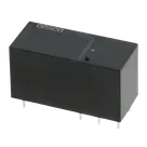
This project involves the use of an Omron G5RL-K1-E-DC12 relay, which is a Single Pole Double Throw (SPDT) or 1-Form-C relay with a 12VDC coil. The components listed under "Project Components" appear to represent the individual pins of the relay, with each pin having a unique designator (though all are prefixed with P, suggesting these represent the pins of the relay in the schematic). The information provided doesn't specify the function of each pin directly but given the typical configuration of a G5RL-K1-E relay, here's a basic explanation based on standard relay pin configurations and common practices:
Pins 1 and 8: These pins are typically the coil pins for the relay. When a 12VDC voltage is applied across these pins, the relay's internal electromagnet is energized, which in turn changes the state of the contacts.
Pins 4 and 3 (usually NO and NC contacts): Pin 4 is commonly the Normally Open (NO) contact, which closes when the coil is energized. Pin 3 is usually the Common (COM) contact. The Normally Closed (NC) contact isn't explicitly identified here but based on standard relay configurations, it could be represented by one of the other pins, possibly pin 9 based on common arrangements.
Pins 2, 5, 6, 7, and 9: The description provided does not specify their functions, but in a typical 5-pin relay layout, these would include the NC contact (as hypothesized above for pin 9), the COM contact (which might be pin 3 instead), and extra terminals that could be for various relay functionalities or configurations, such as for different coil connections or specialized contact arrangements.
Given that no electrical connections have been made in the project yet, and the descriptions of the pins are quite generic, the project is at a very early stage. To proceed with the design, the following steps are suggested:
Identify each pin's function more precisely: This involves confirming which pins serve as the coil connections (likely pins 1 and 8), which pin is the common contact (potentially pin 3), and which are the Normally Open and Normally Closed contacts. This is crucial for correctly wiring the relay in the circuit for the intended control logic.
Establish connections: Once the pin functions are clearly identified, you can start making connections to other components in the circuit. This will involve connecting the coil pins to the control circuit that will switch the relay and connecting the contact pins to the circuit that the relay is intended to control.
Consider external components: Depending on the application, you might need additional components like a flyback diode across the relay coil to protect the control circuit from voltage spikes when the relay is deactivated, resistors for current limiting, or capacitors for noise suppression.
If you have specific functionalities in mind for this relay or need assistance with connecting it within your circuit, feel free to provide more details about the other components and the desired behavior of the circuit.
2y
Someone is typing...
2
1
6
7
5
8
4
2
9
3
No files yet
Reviews
Documents
Documents are markdown text files which describe project goals, capture details, or even simulation outputs.
askrules
copilot