Treat Flux like your intern. Tell it what you'd like to build and it'll get to work. You can also ask it questions, brainstorm ideas, and teach it your preferences. Learn More
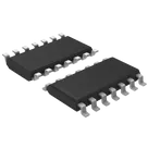
This project appears to be a setup using the DM7404M Integrated Circuit (IC), a hex inverter chip manufactured by Fairchild Semiconductor, in its preliminary stage.
The DM7404M IC is a basic logic element; it takes a digital signal at the input and inverts it at the output. The hex part means there are six separate inverters on this chip.
The chip has 6 input/output pairs given as:
A1 (input) and Y1 (output)
A2 (input) and Y2 (output)
A3 (input) and Y3 (output)
A4 (input) and Y4 (output)
A5 (input) and Y5 (output)
A6 (input) and Y6 (output)
Each of these pairs has their respective symbols with A# corresponding to the input and Y# corresponding to the output.
There are also two power connector pins:
VCC usually connects to the positive supply voltage.
GND commonly connects to the ground or 0V reference point.
Note that there are no connections made within this project yet; it's just the components placed on the schematic. You need to connect these elements and power pins correctly to set up the logic inverters and power the circuit. The design also doesn't currently contain any other components external to the IC; other resistors, capacitors, or signal lines, etc., might be needed based on your overall function and design goals.
2y
Someone is typing...
2
VCC
Y6
A4
A2
Y2
Y3
Y4
GND
A6
A3
A5
Y5
Y1
A1
No files yet
Reviews
Documents
Documents are markdown text files which describe project goals, capture details, or even simulation outputs.
parijats
copilot