Chat
8:55
Project
File
Library
Schematic
Accessed Knowledge (1)
Using Knowledge Base Tool.
Using Schematic Tool.
Looking for "Description" in DFR0478_Web.pdf
Looking for "Features" in DFR0478_Web.pdf
Looking for "Specification" in DFR0478_Web.pdf
Looking for "Power supply" in DFR0478_Web.pdf
Looking for "Pinout" in DFR0478_Web.pdf
Looking for "Operating voltage" in DFR0478_Web.pdf
Looking for "Dimensions" in DFR0478_Web.pdf
Searching for a component.
Searching.
Finished searching for a component.
Below is a clear, design-focused explanation of this project, what it represents in Flux, how the signals are organized, and how you can build on it effectively.
Image
Project overview and purpose
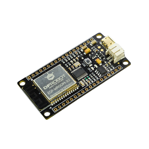
- What this is: A schematic shell exposing the I/O and power rails of the DFRobot FireBeetle ESP32 board DFR0478 as a set of labeled terminals. It is intended to be the anchor in a larger design (carriers, shields, or sensor/actuator add-ons).
- Board intent (from datasheet):
- Working voltage: 3.3 V
- Input voltage: 3.3 V to 5 V
- Power options: USB or 3.7 V external LiPo; “both USB and external DC can charge the Lipo battery directly”
- Deep-sleep current: 10 µA
- Average working current: 80 mA
- MCU module: dual-core ESP32-class (Tensilica LX6), 240 MHz, 520 KB SRAM, 16 Mbit Flash
- Wireless: Wi‑Fi 802.11 b/g/n; Bluetooth v4.2 BR/EDR/BLE
- Interfaces supported (default Arduino mapping): Digital I/O: 10; Analog inputs: 5; SPI: 1; I2C: 1; I2S: 1
- LED_BUILTIN: D9
- Dimensions: 24 × 53 mm; mounting holes inner dia 3.1 mm / outer dia 6 mm
- Development support: Arduino, ESP-IDF, MicroPython; “one-key downloading”
- Source: “FireBeetle ESP32 IOT Microcontroller (Supports Wi‑Fi & Bluetooth) SKU: DFR0478” Datasheet/PDF
What’s in this Flux project now
- This schematic exposes the FireBeetle’s connections purely as terminals (no nets have been defined yet). You can think of it as a breakout/reference symbol to hook up your external circuitry.
- You’ll connect your peripherals to these terminals and then add nets and any needed passives on your schematic.
Core interfaces exposed in the schematic
- Power rails:
- I2C:
- SPI:
- UART:
- I2S/audio and related clock/data lines (as labeled here):
- Analog-labeled inputs:
- Control and utility:
How these pieces interact (step by step)
- Powering the board
- Feed VCC from USB (~5 V) or a 3.7 V LiPo (per datasheet: “supports USB charging” and “both USB and external DC can charge the Lipo battery directly”), and use 3V3 as the regulated logic rail. Tie grounds to GND.
- Datasheet details to consider in your system design:
- Working voltage: 3.3 V
- Input voltage: 3.3 V to 5 V
- Average working current: 80 mA
- Max discharge current (battery path): 600 mA
- Max charge current: 500 mA
- Programming and development
- The board supports “one-key downloading” and works with Arduino, ESP-IDF, and MicroPython (datasheet). This allows straightforward firmware iteration over USB.
- Peripherals and signals
- I2C peripherals connect to SDA/IO21 and SCL/IO22.
- SPI peripherals connect to MOSI/IO23, MISO/IO19, SCK/IO18 and a chosen CS on one of the linked GPIOs.
- UART devices use IO1/TXD and IO3/RXD.
- Audio/I2S or clocked interfaces can use the labeled clock/data lines as appropriate to your firmware configuration.
Key technologies and dependencies
- Wireless (datasheet): Wi‑Fi 802.11 b/g/n; Bluetooth v4.2 BR/EDR/BLE.
- Development environments (datasheet): Arduino, ESP-IDF, MicroPython; “one-key downloading” convenience.
- Timing references (datasheet): On-board 40 MHz and 32.768 kHz crystals.
Design choices, trade-offs, and optimizations
- Dual power input (USB vs LiPo): Flexibility for mobile or tethered applications. Trade-off is managing battery charging currents (datasheet lists maximum charge current 500 mA) and ensuring your system’s peak draw ≤ the “support maximum discharge current” (600 mA) spec.
- 3.3 V logic rail: Clear logic-level boundary for peripherals; requires level translation when interfacing to 5 V-only devices.
- Low-power capabilities: The datasheet cites deep-sleep current of 10 µA; leveraging deep sleep yields excellent battery life, at the cost of wake-up latency and need for careful peripheral state management.
- Compact footprint: At 24 × 53 mm, the board integrates radio + charging + MCU in a small area; thermal and connector real estate on add-on boards should be planned accordingly.
Current project status (in Flux) and challenges
- Schematic status: No nets have been defined yet; all pins are currently standalone terminals for DFR0478.
- Next tasks you’ll likely tackle:
- Define power nets and distribution (decide whether your add-on uses VCC directly or the regulated 3V3).
- Wire your peripherals to the appropriate terminals and name nets for clarity.
- Add required passives for bus integrity (see below).
- Use the canonical Ground symbol for ground connections (best practice to improve readability and copper fills).
Performance considerations (system-level, based on datasheet)
- Power budget: Size upstream supplies and traces for at least the datasheet’s average current (80 mA) plus peripheral loads; if running from battery, be mindful of the board’s “support maximum discharge current” (600 mA) and “support maximum charge current” (500 mA).
- RF co-existence: The board integrates Wi‑Fi/BLE; keep noisy high-current switching or long-antenna cables isolated on your carrier where possible, and avoid routing aggressive clocks immediately adjacent to antenna keep-out on the physical board (applies during layout of your add-on).
Real-world applications this supports well
- Battery-powered IoT nodes with Wi‑Fi/BLE.
- Sensor/actuator control with I2C/SPI/UART add-ons.
- Audio streaming/processing demos via I2S as supported in your firmware stack.
- Rapid prototyping in Arduino/MicroPython with ultra-low-power standby modes.
Areas for improvement and future enhancements
- Power decoupling on your add-ons:
- Per best-practice guidance, include a parallel combination of a 100nF Capacitor, a 1uF Capacitor, and a 10uF Capacitor near each device’s supply pins to cover both high- and low-frequency transients.
- When selecting capacitors, ensure they operate at no more than 60% of their maximum rated voltage.
- I2C bus robustness:
- Add pull-ups (e.g., 4.7k Resistor) to SDA/IO21 and SCL/IO22 on the 3.3 V rail (if not already present in your stack).
- ESD/Transient protection for field wiring:
- Clear net naming and documentation:
- Name nets to match firmware roles (e.g., “IMU_SDA”, “IMU_SCL”, “FLASH_CS”) and tag voltage domains.
- Schematic readability:
- Replace the terminal-based ground with the canonical Ground symbol throughout for clarity and better PCB copper handling.
Scalability ideas
- Standardized headers: Add consistent pin headers for I2C, SPI, UART, power breakout to scale to multiple peripherals easily.
- Modular add-ons: Split sensors/actuators into reusable modules; maintain consistent net names and interface pin orders.
- Power domain planning: If peripherals draw bursts beyond the FireBeetle’s discharge support, consider local regulators and bulk storage on add-on boards sized to your transient load.
Design and implementation steps you can follow next
- Power architecture:
- Buses and peripherals:
- Grounding:
- Use Ground symbols for all returns; plan for a continuous ground reference on the PCB.
- Firmware alignment:
- Map nets to the terminal labels you connect so your code’s pin configuration and the schematic remain consistent.
If you want, I can:
- List and group all terminals you plan to use and propose exact net names.
- Suggest a minimal passive set (decoupling and pull-ups) tailored to your specific peripherals.
- Help wire this schematic step-by-step so it’s ready for PCB layout.
162 days
Ready.
IO11/CMD
GND
DI/IO16
A0/IO36
IO10/D6
A3/IO35
IO9/D5
MCLK/IO12
A2/IO34
IO7/SD0
IO13/D7
DO/IO4
VCC
MISO/IO19
IO26/D3
RST
AREF
SDA/IO21
IO0
3V3
A1/IO39
MOSI/IO23
IO5/D8
SCK/IO18
IO1/TXD
IO2/D9
MH4
IO8/SD1
IO3/RXD
MH3
MH2
A4/IO15
SCL/IO22
BCLK/IO14
IO27/D4
IO6/CLK
LRCK/IO17
NC
MH1
IO25/D2
Reviews

- Wirelessly connects nets on schematic. Used to organize schematics and separate functional blocks. To wirelessly connect net portals, give them same designator. #portaljharwinbarrozo43.0M
- Wirelessly connects power nets on schematic. Identical to the net portal, but with a power symbol. Used to organize schematics and separate functional blocks. To wirelessly connect power net portals, give them the same designator. #portal #powerjharwinbarrozo11.4M
- A generic fixed resistor for rapid developing circuit topology. Save precious design time by seamlessly add more information to this part (value, footprint, etc.) as it becomes available. Standard resistor values: 1.0Ω 10Ω 100Ω 1.0kΩ 10kΩ 100kΩ 1.0MΩ 1.1Ω 11Ω 110Ω 1.1kΩ 11kΩ 110kΩ 1.1MΩ 1.2Ω 12Ω 120Ω 1.2kΩ 12kΩ 120kΩ 1.2MΩ 1.3Ω 13Ω 130Ω 1.3kΩ 13kΩ 130kΩ 1.3MΩ 1.5Ω 15Ω 150Ω 1.5kΩ 15kΩ 150kΩ 1.5MΩ 1.6Ω 16Ω 160Ω 1.6kΩ 16kΩ 160kΩ 1.6MΩ 1.8Ω 18Ω 180Ω 1.8KΩ 18kΩ 180kΩ 1.8MΩ 2.0Ω 20Ω 200Ω 2.0kΩ 20kΩ 200kΩ 2.0MΩ 2.2Ω 22Ω 220Ω 2.2kΩ 22kΩ 220kΩ 2.2MΩ 2.4Ω 24Ω 240Ω 2.4kΩ 24kΩ 240kΩ 2.4MΩ 2.7Ω 27Ω 270Ω 2.7kΩ 27kΩ 270kΩ 2.7MΩ 3.0Ω 30Ω 300Ω 3.0KΩ 30KΩ 300KΩ 3.0MΩ 3.3Ω 33Ω 330Ω 3.3kΩ 33kΩ 330kΩ 3.3MΩ 3.6Ω 36Ω 360Ω 3.6kΩ 36kΩ 360kΩ 3.6MΩ 3.9Ω 39Ω 390Ω 3.9kΩ 39kΩ 390kΩ 3.9MΩ 4.3Ω 43Ω 430Ω 4.3kΩ 43KΩ 430KΩ 4.3MΩ 4.7Ω 47Ω 470Ω 4.7kΩ 47kΩ 470kΩ 4.7MΩ 5.1Ω 51Ω 510Ω 5.1kΩ 51kΩ 510kΩ 5.1MΩ 5.6Ω 56Ω 560Ω 5.6kΩ 56kΩ 560kΩ 5.6MΩ 6.2Ω 62Ω 620Ω 6.2kΩ 62KΩ 620KΩ 6.2MΩ 6.8Ω 68Ω 680Ω 6.8kΩ 68kΩ 680kΩ 6.8MΩ 7.5Ω 75Ω 750Ω 7.5kΩ 75kΩ 750kΩ 7.5MΩ 8.2Ω 82Ω 820Ω 8.2kΩ 82kΩ 820kΩ 8.2MΩ 9.1Ω 91Ω 910Ω 9.1kΩ 91kΩ 910kΩ 9.1MΩ #generics #CommonPartsLibraryjharwinbarrozo1.5M
- A generic fixed capacitor ideal for rapid circuit topology development. You can choose between polarized and non-polarized types, its symbol and the footprint will automatically adapt based on your selection. Supported options include standard SMD sizes for ceramic capacitors (e.g., 0402, 0603, 0805), SMD sizes for aluminum electrolytic capacitors, and through-hole footprints for polarized capacitors. Save precious design time by seamlessly add more information to this part (value, footprint, etc.) as it becomes available. Standard capacitor values: 1.0pF 10pF 100pF 1000pF 0.01uF 0.1uF 1.0uF 10uF 100uF 1000uF 10,000uF 1.1pF 11pF 110pF 1100pF 1.2pF 12pF 120pF 1200pF 1.3pF 13pF 130pF 1300pF 1.5pF 15pF 150pF 1500pF 0.015uF 0.15uF 1.5uF 15uF 150uF 1500uF 1.6pF 16pF 160pF 1600pF 1.8pF 18pF 180pF 1800pF 2.0pF 20pF 200pF 2000pF 2.2pF 22pF 20pF 2200pF 0.022uF 0.22uF 2.2uF 22uF 220uF 2200uF 2.4pF 24pF 240pF 2400pF 2.7pF 27pF 270pF 2700pF 3.0pF 30pF 300pF 3000pF 3.3pF 33pF 330pF 3300pF 0.033uF 0.33uF 3.3uF 33uF 330uF 3300uF 3.6pF 36pF 360pF 3600pF 3.9pF 39pF 390pF 3900pF 4.3pF 43pF 430pF 4300pF 4.7pF 47pF 470pF 4700pF 0.047uF 0.47uF 4.7uF 47uF 470uF 4700uF 5.1pF 51pF 510pF 5100pF 5.6pF 56pF 560pF 5600pF 6.2pF 62pF 620pF 6200pF 6.8pF 68pF 680pF 6800pF 0.068uF 0.68uF 6.8uF 68uF 680uF 6800uF 7.5pF 75pF 750pF 7500pF 8.2pF 82pF 820pF 8200pF 9.1pF 91pF 910pF 9100pF #generics #CommonPartsLibraryjharwinbarrozo1.5M
- A generic fixed inductor for rapid developing circuit topology. *You can now change the footprint and 3D model at the top level anytime you want. This is the power of #genericsjharwinbarrozo15.4k
- An electrical connector acting as reusable interface to a conductor and creating a point where external circuits can be connected.Terminal
- 47 kOhms ±5% 0.125W, 1/8W Chip Resistor 0805 (2012 Metric) Automotive AEC-Q200 Thick Film #forLedBlinkjharwinbarrozo1.2M
- 10uF Capacitor Aluminum Polymer 20% 16V SMD 5x5.3mm #forLedBlink #commonpartslibrary #capacitor #aluminumpolymer #radialcanjharwinbarrozo1.2M
- Yellow 595nm LED Indication - Discrete 1.7V 1206 (3216 Metric) #forLedBlinkjharwinbarrozo1.1M


Inspect
DFR0478
Controls
Properties
Part Type
Evaluation Board
Manufacturer Name
DFRobot
Manufacturer Part Number
DFR0478
Designator Prefix
U
Assets
 DFR0478
id=DFR0478 Symbol.svg
- DFR0478.stp
id=3D_DFR0478
- FIREBEETLE_ESP32.kicad_mod
id=FP_FIREBEETLE_ESP32
- DFR0478.png
id=DFR0478
Default
3d Model
Footprint
Thumbnail

Welcome 👋
Flux accelerates your PCB design with AI.
Create your account to start using this component and bring your ideas to life.
axl2023
copilot
axl2023
copilot
- Módulo nRF24L01: Este módulo proporcionará la funcionalidad inalámbrica para enviar y recibir comandos a distancia.
- Driver de motor: Un módulo controlador de motor (como el L298N o el TB6612FNG) es necesario para interactuar con el motor DC, ya que el ESP32 por sí solo no puede proporcionar la corriente o voltaje necesario para la mayoría de los motores DC.
- Motor DC: El componente que quieres controlar.
Conexiones para nRF24L01- Connect P:MOSI/IO23 to nRF24L01:MOSI
- Connect P:MISO/IO19 to nRF24L01:MISO
- Connect P:SCK/IO18 to nRF24L01:SCK
- Connect P:IO5/D8 to nRF24L01:CSN
- Connect P:IO2/D9 to nRF24L01:CE
- Además, asegúrate de conectar GND a GND y VCC (del nRF24L01) a 3V3 en el FireBeetle ESP32.
Conexiones del Driver de Motor y Motor DC- Conectar el VCC y GND del driver de motor a una fuente de alimentación adecuada que coincida con las especificaciones de tu motor DC.
- Conectar los terminales del motor DC a las salidas del módulo de control de motor.
- Conectar los pines de control del módulo de control de motor a pines GPIO disponibles en el FireBeetle ESP32. Por ejemplo, si usas un L298N, puedes usar los pines IO0 y IO4 (pines GPIO digitales) para controlar la dirección y velocidad (a través de PWM).
SoftwareRF24. Para el FireBeetle ESP32, usarás el IDE de Arduino o un entorno similar para programarlo. Aquí hay un esquema básico de lo que necesitarás en tu código: