Treat Flux like your intern. Tell it what you'd like to build and it'll get to work. You can also ask it questions, brainstorm ideas, and teach it your preferences. Learn More
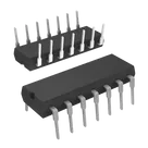
To wire a NOR gate using the CD4001UBE IC, we will make use of one of its four NOR gate channels. Assuming you want to use the first NOR gate in the IC, let's proceed with that. The CD4001UBE IC pins for the first NOR gate are as follows:
Pin 1: Input A
Pin 2: Input B
Pin 3: Output Q
Pin 7: Ground (VSS)
Pin 14: Positive Supply Voltage (VDD)
Given the components listed in your project, let's assign:
A (Pin 1) to component A
B (Pin 2) to component B
Output (Pin 3) to component J
Ground (VSS, Pin 7) to component VSS
VDD (Pin 14) to component VDD
Connections:
Connect A:1 to U:1. (Input A of NOR gate)
Connect B:1 to U:2. (Input B of NOR gate)
Connect J:1 to U:3. (Output of NOR gate)
Connect VSS:1 to U:7. (Ground)
Connect VDD:1 to U:14. (Positive Supply Voltage)
These connections establish the basic hookup for a single NOR gate on the CD4001UBE IC. Make sure to provide a power supply to VDD and ground VSS. The truth table for a NOR gate is such that the output Q (connected to J:1 in your setup) will be low (0) only if both inputs A and B are low (0); otherwise, Q will be high (1).
If you've meant to use another channel on the CD4001UBE or have specific requirements for different inputs/outputs beyond the basic configuration, let me know, and we can adjust accordingly!
2y
Someone is typing...
2
E
C
VSS
B
L
H
A
M
F
K
D
J
VDD
G
No files yet
Reviews
Documents
Documents are markdown text files which describe project goals, capture details, or even simulation outputs.
thien43
copilot
ABJVSSVDDA:1toU:1. (Input A of NOR gate)B:1toU:2. (Input B of NOR gate)J:1toU:3. (Output of NOR gate)VSS:1toU:7. (Ground)VDD:1toU:14. (Positive Supply Voltage)VDDand groundVSS. The truth table for a NOR gate is such that the outputQ(connected toJ:1in your setup) will be low (0) only if both inputsAandBare low (0); otherwise,Qwill be high (1).