Smart IoT Water Level Controller Design
Image
Image
Image
Image
Thought for 15 sec
I’ll use these reference images to refine the documented architecture and PCB feature list, especially the single-board labels, touch/network edition, relay/protection zones, and user-control layout. I’ll update the project files rather than duplicating the long details in chat.
Worked for 1 min 28 sec
I updated the project requirements using the uploaded reference images and added a new Reference Image Assessment.
I also updated the Project Specification with the image-derived features: touch/network edition labeling, front-panel LEDs, five-key backup UI, relay/protection zones, and clear PCB service markings.
Start schematic design
Choose safe sensors
Add component list
Explain isolation boundary
Design HV board later
Refine this doc
Ask about this doc
Project Specification:IRAA ESP32 IoT Water Controller
Project Overview
Status: Draft
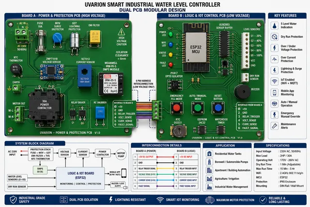
This project is a premium Smart IoT Water Level Controller for residential, agricultural, and light industrial pump control. The target design uses a dual-PCB architecture: a high-voltage power and motor-control board separated from a low-voltage ESP32 logic and user-interface board.
Intended Use
The controller is intended to monitor an overhead water tank, automatically start and stop a pump, protect the motor from unsafe conditions, and report status through Wi-Fi. It is intended as a commercial IRAA / UVARION product concept with stronger safety and reliability than a low-cost single-board controller.
What the Device Should Do
- Detect tank level at 20%, 40%, 60%, 80%, and 100% points.
- Start the motor automatically when the tank level is low.
- Stop the motor automatically when the tank is full.
- Detect source-water dry-run conditions and stop the motor.
- Detect AC under-voltage and over-voltage and prevent unsafe motor operation.
- Measure motor current for overload, dry-run signature detection, and energy monitoring.
- Provide Auto, Manual, Emergency Fill, Reset, and Bypass controls.
- Show local status using LEDs, buzzer, and a 4.2 inch TFT touch display.
- Send status, alarms, and history through Wi-Fi using MQTT or an app backend.
- Support OTA firmware updates.
Main Features
- ESP32-based Wi-Fi and Bluetooth controller.
- Dual-PCB safety architecture.
- Five tank-level inputs plus dry-run source-water input.
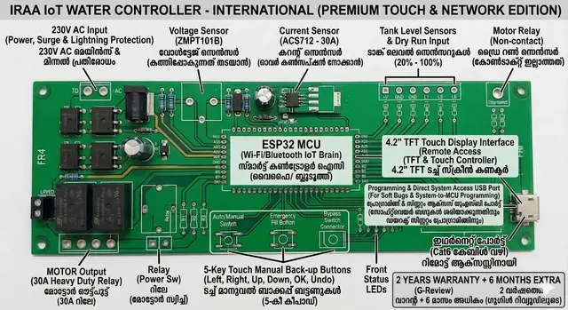
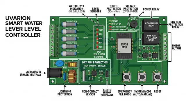
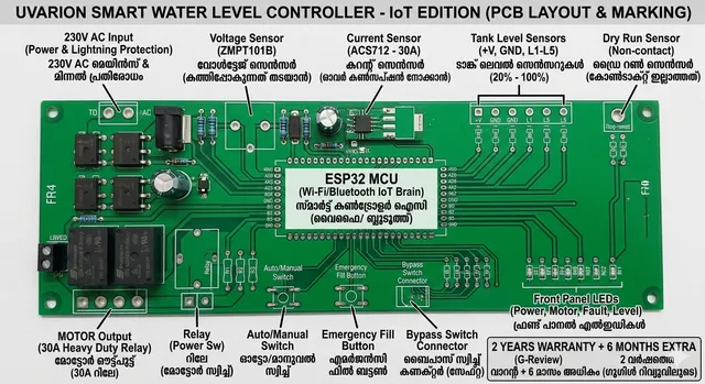
- Image-reference layout variants include a premium touch/network edition, a smart lever/level controller layout, and an IoT PCB marking layout.
- Voltage monitoring using an isolated AC voltage sensor module or equivalent circuit.
- Current monitoring using ACS712, SCT013, or a production-grade isolated current sensor.
- Relay or contactor driver output for pump control.
- Dedicated motor relay or contactor output area, with heavy-duty relay/contactors kept physically separated from ESP32 logic.
- Surge and lightning protection using fuse, MOV, GDT, EMI filtering, and NTC inrush limiting.
- Clearly labeled AC input, motor output, tank sensor, dry-run sensor, voltage sensor, current sensor, relay power, and TFT connectors.
- RTC for scheduling and event timestamps.
- Non-volatile memory for settings and calibration.
- Touch display option for premium model.
- Front-panel status LEDs for power, motor, dry-run, voltage fault, tank level, and general fault status.
System Architecture
Diagram
Hardware Subsystems
Board A: High Voltage Power and Motor Board
- 230 VAC input connector with fuse.
- MOV and GDT surge protection.
- EMI filtering and NTC inrush limiter.
- Isolated AC-DC SMPS for low-voltage power.
- Voltage sensing with isolation.
- Current sensing with safe isolation.
- Relay or contactor output for motor control.
- Isolation boundary to the logic board.
Board B: Low Voltage Logic and User Interface Board
- ESP32 module, preferably a certified module with integrated antenna.
- 3.3 V regulator and local decoupling.
- Tank level and dry-run sensor input protection.
- TFT touch display interface.
- LEDs, buzzer, and buttons.
- RTC such as DS3231.
- Non-volatile memory if required beyond ESP32 flash/NVS.
- Programming and debug access.
Interfaces and Connections
- AC mains input: phase, neutral, earth where available.
- Pump output: phase and neutral through relay or contactor wiring.
- Inter-board power: isolated low-voltage DC from Board A to Board B.
- Inter-board signals: isolated voltage sense, current sense, relay command, and fault/status lines as needed.
- Tank probes or sensor connector: S1 to S5 plus common/reference.
- Dry-run input connector.
- TFT connector.
- Buttons: Auto/Manual, Emergency Fill, Reset, Bypass.
- Five-key manual backup concept from the reference images: Left, Right, Up, Down, OK, and Undo for menu navigation when a touch display is not used.
- Dedicated front-panel LED connector for power, motor, fault, and tank-level indication.
- Buzzer and fault/status LEDs.
- Wi-Fi antenna zone: ESP32 antenna must face a board edge with no copper keepout.
Power and Runtime Expectations
The device is mains powered. Battery runtime is not required unless a future backup option is added. The logic board should remain powered whenever mains is present so it can log faults and display status even when the pump is off.
Power Tree and Power Budget
Initial target power tree:
Diagram
Preliminary estimated loads:
Table
| Rail | Load | Estimated Current |
|---|---|---|
| 3.3 V | ESP32 Wi-Fi peak | 500 mA peak |
| 3.3 V | RTC and memory | 5 mA |
| 3.3 V | sensor inputs and pull-ups | 20 mA |
| 3.3 V | LEDs if powered from 3.3 V | 50 mA |
| 5 V | TFT display | 150 mA to 300 mA estimate |
| 5 V | buzzer and driver circuits | 50 mA to 150 mA estimate |
| 5 V or 12 V | relay or contactor interface | depends on selected relay/contactor |
Initial recommendation: use an isolated AC-DC module rated at least 5 V, 2 A for prototype margin, then derive 3.3 V with a regulator sized for at least 700 mA peak. Final ratings must be recalculated after selecting the exact TFT, relay/contactor coil voltage, sensors, and isolation circuits.
Manufacturing and Assembly Expectations
- Dual-PCB architecture is preferred for safety, serviceability, and noise reduction.
- High-voltage PCB must maintain mains creepage and clearance distances and include isolation slots where appropriate.
- Low-voltage PCB can use compact SMD assembly, but connectors and controls should be field-serviceable.
- Add test points for 5 V, 3.3 V, GND, relay command, voltage sense, current sense, and key sensor inputs.
- Use certified AC-DC power module where possible to reduce mains safety risk.
Firmware-Relevant Hardware Requirements
- Stable ESP32 boot circuit with EN pull-up, reset button, GPIO0 boot button, and programming access.
- MQTT support for Home Assistant, Node-RED, Blynk, ThingsBoard, or a custom app.
- OTA firmware update support.
- NVS or external EEPROM for calibration, thresholds, Wi-Fi credentials, and fault history.
- RTC for pump schedules, runtime logging, and timestamped alarms.
- Fault state machine for dry-run, over-voltage, under-voltage, overload, bypass, and manual mode.
Physical Design Expectations
- Two physically separated boards or one enclosure with separated compartments.
- High-voltage terminals must be shielded and clearly labeled.
- Low-voltage UI board should place TFT, buttons, and LEDs on the enclosure front panel.
- ESP32 antenna must be kept away from metal enclosure walls, large copper pours, and high-current switching areas.
- Reference-image PCB marking style should be preserved in the production design: large connector labels, bilingual/local-language user-facing labels where needed, and clear service markings for AC input, motor output, sensors, relays, and USB/programming access.
- Keep the high-voltage protection and relay zones near the AC/motor terminals, and keep ESP32, display, buttons, and sensor connectors in the low-voltage service area.
Important Design Decisions
- Use dual-PCB architecture for the premium industrial product.
- Use ESP32 module instead of bare ESP32 chip to simplify RF design and improve Wi-Fi reliability.
- Use isolation between mains sensing/control and ESP32 logic.
- Use a contactor or industrial relay for high-current motor loads rather than routing motor current through the logic PCB.
- Treat the 4.2 inch TFT touch display as the premium UI option.
- Preserve the reference concepts as visual targets, but treat them as product-layout inspiration rather than safety-verified electrical schematics.
Assumptions
- Nominal mains supply is 230 VAC.
- Initial voltage protection thresholds are 170 VAC under-voltage and 260 VAC over-voltage.
- Motor load may be up to 30 A, so final switching should use an external contactor or appropriately certified relay assembly.
- Exact tank sensors, TFT module, contactor coil voltage, enclosure, and compliance target are not yet selected.
- This first revision captures architecture and requirements before detailed schematic component selection.
Change Notes
- Created initial specification from the user's Smart IoT Water Level Controller concept.
- Captured the recommendation to combine dual-PCB industrial architecture, ESP32 plus MQTT, 4.2 inch TFT, RTC, EEPROM/settings storage, surge protection, dry-run protection, and mobile alerts.
- Updated from uploaded reference images: added labeled connector expectations, front-panel LED connector, five-key backup UI, touch/network edition marking, relay/protection zone separation, and PCB service-labeling requirements.

Welcome 👋
Flux helps you build PCBs faster with an AI teammate!
Create your account to collaborate, stay updated, fork your own version, and get instant answers from our AI agent.