Smart IoT Water Level Controller Design
Image
Image
Image
Image
Thought for 15 sec
I’ll use these reference images to refine the documented architecture and PCB feature list, especially the single-board labels, touch/network edition, relay/protection zones, and user-control layout. I’ll update the project files rather than duplicating the long details in chat.
Worked for 1 min 28 sec
I updated the project requirements using the uploaded reference images and added a new Reference Image Assessment.
I also updated the Project Specification with the image-derived features: touch/network edition labeling, front-panel LEDs, five-key backup UI, relay/protection zones, and clear PCB service markings.
Start schematic design
Choose safe sensors
Add component list
Explain isolation boundary
Design HV board later
Refine this doc
Ask about this doc
Power and Architecture Notes
Safety Architecture
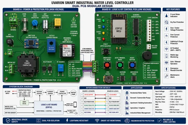
The recommended product architecture is two-board separation:
- High-voltage board: mains input, protection, AC sensing, current sensing, isolated power supply, and motor contactor interface.
- Low-voltage logic board: ESP32, UI, buttons, sensor inputs, RTC, memory, buzzer, and communications.
This separation reduces electric shock risk, keeps high-current noise away from the ESP32, and makes the product easier to service.
Preliminary Power Tree
Diagram
Initial Load Estimate
These are planning estimates only. Final values must be updated after exact part selection and datasheet review.
Table
| Rail | Load | Typical Estimate | Peak Estimate | Notes |
|---|---|---|---|---|
| 3.3 V | ESP32 module | 120 mA | 500 mA | Wi-Fi transmit peaks can be high. |
| 3.3 V | RTC plus memory | 2 mA | 5 mA | DS3231 and EEPROM or NVS support. |
| 3.3 V | level input network | 5 mA | 20 mA | Depends on probe method and pull-up values. |
| 3.3 V | status LEDs | 0 mA to 30 mA | 50 mA | Could also be powered from 5 V through drivers. |
| 5 V | TFT touch display | 150 mA | 300 mA | Must verify exact display module. |
| 5 V | buzzer and indicators | 20 mA | 150 mA | Depends on buzzer type and LED drive. |
| 5 V | relay driver interface | 20 mA | TBD | A contactor coil may be external AC and not powered by this rail. |
Preliminary Rail Sizing
- 3.3 V regulator target: at least 700 mA peak capability.
- 5 V isolated AC-DC target: at least 2 A for prototype margin if the TFT and relay/driver are powered from 5 V.
- If the contactor has a high-power DC coil, the coil supply should be separated from the ESP32 logic rail.
- If using an LDO from 5 V to 3.3 V at 300 mA typical, thermal dissipation is about 0.51 W, which is too high for many tiny SOT-23 regulators. A larger LDO package or a buck regulator should be considered if continuous ESP32 plus peripherals exceed about 250 mA.
Mains and Motor Protection Notes
- Use a properly rated fuse before surge and filter components.
- MOV must be rated for 230 VAC mains service.
- GDT selection depends on surge requirements and earthing arrangement.
- EMI filter must be safety-rated for mains use.
- NTC inrush limiter must be sized for normal load current and enclosure temperature.
- Motor current path should not be routed through the low-voltage logic PCB.
- A 30 A motor output should use a certified contactor or relay assembly with suitable creepage, clearance, thermal design, and terminal rating.
Isolation Notes
- AC voltage sensing should be isolated from ESP32 ADC inputs.
- Current sensing should be isolated or non-invasive. SCT013 current transformer is safer for high-current AC loads than a board-mounted Hall module when the motor current is large.
- Relay or contactor drive should use optocoupler or isolated driver where needed.
- Inter-board connectors must preserve the high-voltage to low-voltage isolation boundary.
Open Decisions Before Schematic Part Selection
- Exact ESP32 module: ESP32-S3-WROOM is recommended for native USB and sufficient GPIO.
- TFT display interface: SPI is recommended to reduce pin count.
- Tank sensing method: conductive probes, float switches, capacitive sensors, or isolated digital inputs.
- Dry-run sensing method: source probe, flow sensor, pressure switch, or current-signature algorithm.
- Current sensor: SCT013 style CT for high-current AC is recommended for safety.
- Voltage sensor: isolated voltage transformer/module or certified measurement front end.
- Motor output: external AC contactor controlled by low-voltage driver is recommended for 30 A loads.
- Compliance target: local safety certification requirements must be decided before production.
Current Design Direction
For the first schematic revision, build a safe low-voltage controller board plus isolated interfaces to a high-voltage board. Treat high-voltage mains switching and sensing as connectorized, isolated subsystems unless exact certified HV parts are selected.

Welcome 👋
Flux helps you build PCBs faster with an AI teammate!
Create your account to collaborate, stay updated, fork your own version, and get instant answers from our AI agent.