Project Overview and Design Analysis
1:34
Project
Below is an overview of the project based on its current schematic and parts list:
Project Name:
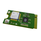
M.2 KeyB 2242 Card
M.2 KeyB 2242 Card
Purpose & Concept:
This project is intended to serve as a design for an M.2 Key B card. Although the project description is still the initial placeholder ("Welcome to your new project. Imagine what you can build here."), the schematic gives clues about its intended functionality. It combines processing, wireless communication, nonvolatile storage, and connectivity through an edge connector—features that are common in embedded modules that interface with larger systems.
This project is intended to serve as a design for an M.2 Key B card. Although the project description is still the initial placeholder ("Welcome to your new project. Imagine what you can build here."), the schematic gives clues about its intended functionality. It combines processing, wireless communication, nonvolatile storage, and connectivity through an edge connector—features that are common in embedded modules that interface with larger systems.
Core Components & Their Roles:
Table
| Component & Link | Role in Design |
|---|---|
| RP2040 (U2) | Acts as the central microcontroller. It has multiple GPIOs, supports high-speed interfaces, and serves as the processing and control core. |
| LoRa-E5 (STM32WLE5JC) (U1) | Provides wireless connectivity via LoRaWAN. Likely interfaces with the microcontroller for sending/receiving data. |
| W25Q128JVSIQ (U3) | External flash memory for nonvolatile storage. It interfaces with the microcontroller using a SPI/QSPI bus. |
| FL1200112 - 12MHz Crystal (Y) | Supplies a precise clock reference for the system, which is crucial for timing—especially in communication and digital logic functions. |
| Edge Connector (M.2 Key B) | Provides the physical interface whose contacts expose signals and power lines from the card to an external host. |
| Multiple Capacitors (e.g., Generic Capacitors at values of 100nF, 1µF, 27pF) | Used for decoupling, signal filtering, and stabilizing power supply rails. The distributed arrangement (one per power pin, where applicable) helps ensure signal integrity. |
| Multiple Resistors (e.g., R7, R5, R6, etc.) | Serve in roles such as setting bias points, current limiting (e.g., for the LED), and forming voltage divider circuits. |
| SW2 | Likely used for user input (e.g., reset or a mode selection). |
| D1 | Serves as a status or indication light. Its current is controlled via current-limiting resistor(s). |
| Ground and Power Net Portals (+3V3, +1V1) | Distribute regulated supply voltages and provide common connections for signal references throughout the design. |
Signal & Power Interactions:
-
Microcontroller Integration:
The RP2040 (U2) is connected to many of the nets in the design. Its pins are assigned to power, ground, GPIO, analog inputs (as seen with ADC nets), and digital interfaces (such as QSPI lines to the flash memory and clock signals from the crystal). Integration with the LoRa module (LoRa-E5 (U1)) suggests a control/data exchange between these two blocks. -
Peripheral Communication:
The flash memory (W25Q128JVSIQ (U3)) uses high-speed serial interfaces (for example, QSPI), and several nets explicitly interconnect these ports with the RP2040, ensuring program data and other storage functions are supported. Net names like "QSPI_SD0" through "QSPI_SD3" and "QSPI_SCLK" indicate clear assignment of these signals. -
Decoupling & Filtering:
Multiple generic capacitors in different parts of the schematic—for power inputs, analog signals, and digital decoupling—help to smooth out voltage variations and filter out high-frequency noise. Their distribution is vital to support stable operation of both the microcontroller and the RF module. -
Connector Interface:
The edge connector defined for the M.2 key B interface means that the design not only integrates internal functionalities (microcontroller, flash, and wireless) but also considers the needs for external connectivity. This may allow the card to be plugged into a host board where additional functionalities (e.g., power management, extended I/O) can be implemented.
Design & Implementation Considerations:
-
Schematic Organization:
The project’s schematic is broken down into clear nets for power distribution (like GND, +3V3, and +1V1) and signal routing (using designated net areas for QSPI, USB, GPIO, etc.). This organization helps in reviewing and verifying interconnections. -
Component Placement & Reviews:
The design includes review categories (for passive components, manufacturing, and design rule checks). Although several reviews (such as the Airwire connectivity review) have flagged errors, these help pinpoint potential layout or connection issues that must be addressed. -
Trade-offs and Optimizations:
- Integration vs. Modularity: Using the RP2040 combined with a dedicated LoRa module and external flash keeps the processing core simple while offloading specific tasks (wireless communication and storage) to dedicated components.
- Size & Decoupling: The use of SMD components, particularly in the 0402 package, optimizes board space. However, tight layouts require careful decoupling and attention to PCB trace routing to avoid issues such as overlapping copper or airwire errors.
-
Potential Challenges:
- Connectivity Issues: Some airwire errors suggest that certain pins (e.g., on the RP2040 or associated with the flash interface) might not be optimally connected. These will need verification against datasheet recommendations, especially for high-speed interfaces.
- Power Integrity: Ensuring proper decoupling over the various operating conditions (especially given the mix of digital RF and low-noise analog domains) can be critical.
- Manufacturing Tolerances: The edge connector for the M.2 interface and the use of multiple SMD parts must be reviewed for footprint compatibility and assembly reliability.
-
Real-World Applications & Future Enhancements:
This project is well suited for embedded systems where a compact, multifunctional card is required—for example, IoT gateways, wireless sensor nodes, or multifunctional mini-PCBs. Future enhancements might include:- Expanding the number of interfacing options (for sensors or additional communication protocols).
- Optimizing the layout to meet stringent RF performance requirements, especially for the LoRa transceiver.
- Refining power management circuits to support battery operation or dynamic power scaling.
- Addressing layout and connectivity errors flagged during design rule check reviews, to improve reliability and manufacturability.
Summary:
The M.2 KeyB 2242 Card is designed as a compact, multifunctional board that integrates processing (via the RP2040), wireless communication (LoRa module), and nonvolatile storage (flash memory) with a robust edge connector interface. The design emphasizes careful signal handling, power integrity, and component interconnection. While the overall architecture is promising, attention to net connectivity, decoupling, and proper review of flagged design issues will be key to ensuring reliable performance.
The M.2 KeyB 2242 Card is designed as a compact, multifunctional board that integrates processing (via the RP2040), wireless communication (LoRa module), and nonvolatile storage (flash memory) with a robust edge connector interface. The design emphasizes careful signal handling, power integrity, and component interconnection. While the overall architecture is promising, attention to net connectivity, decoupling, and proper review of flagged design issues will be key to ensuring reliable performance.
This detailed analysis highlights current design choices, possible trade-offs, and areas for future improvement.
Project Context Update
Key Challenges
Design Enhancements
367 days
Ready.
C13
Capacitance
100n F
GPIO5
C9
Capacitance
100n F
GPIO24
C12
Capacitance
1u F
LORA_RX
GPIO14
GPIO11
GPIO2
C14
Capacitance
100n F
QSPI_SD1
QSPI_SD0
GPIO4
GPIO8
C11
Capacitance
1u F
GPIO26
GPIO27
C10
Capacitance
100n F
QSPI_SD3
GPIO10
GPIO7
C3
Capacitance
100n F
C5
Capacitance
100n F
GPIO3
LORA_TX
GPIO15
LORA_TX
LORA_NRST
USB_D+
QSPI_SD1
C7
Capacitance
100n F
USB_D-
GPIO23
GPIO13
XOUT
QSPI_SD2
C8
Capacitance
100n F
LORA_RX
C2
Capacitance
100n F
QSPI_SD2
XIN
GPIO29
QSPI_SS
QSPI_SD3
QSPI_SCLK
GPIO9
QSPI_SD0
GPIO22
XOUT
C4
Capacitance
100n F
C6
Capacitance
100n F
GPIO6
U2
Note 3
+3V3
+1V1
Note 5
+3V3
+1V1
+1V1
Note 2
Note 6
Note 4
R6
Resistance
27.4 Ω
R3
Resistance
27.4 Ω
R2
Resistance
1k5 Ω
R4
Resistance
1k Ω
+3V3
D1
Color
Green
Reviews

- Wirelessly connects nets on schematic. Used to organize schematics and separate functional blocks. To wirelessly connect net portals, give them same designator. #portaljharwinbarrozo43.0M
- Wirelessly connects power nets on schematic. Identical to the net portal, but with a power symbol. Used to organize schematics and separate functional blocks. To wirelessly connect power net portals, give them the same designator. #portal #powerjharwinbarrozo11.4M
- A generic fixed resistor for rapid developing circuit topology. Save precious design time by seamlessly add more information to this part (value, footprint, etc.) as it becomes available. Standard resistor values: 1.0Ω 10Ω 100Ω 1.0kΩ 10kΩ 100kΩ 1.0MΩ 1.1Ω 11Ω 110Ω 1.1kΩ 11kΩ 110kΩ 1.1MΩ 1.2Ω 12Ω 120Ω 1.2kΩ 12kΩ 120kΩ 1.2MΩ 1.3Ω 13Ω 130Ω 1.3kΩ 13kΩ 130kΩ 1.3MΩ 1.5Ω 15Ω 150Ω 1.5kΩ 15kΩ 150kΩ 1.5MΩ 1.6Ω 16Ω 160Ω 1.6kΩ 16kΩ 160kΩ 1.6MΩ 1.8Ω 18Ω 180Ω 1.8KΩ 18kΩ 180kΩ 1.8MΩ 2.0Ω 20Ω 200Ω 2.0kΩ 20kΩ 200kΩ 2.0MΩ 2.2Ω 22Ω 220Ω 2.2kΩ 22kΩ 220kΩ 2.2MΩ 2.4Ω 24Ω 240Ω 2.4kΩ 24kΩ 240kΩ 2.4MΩ 2.7Ω 27Ω 270Ω 2.7kΩ 27kΩ 270kΩ 2.7MΩ 3.0Ω 30Ω 300Ω 3.0KΩ 30KΩ 300KΩ 3.0MΩ 3.3Ω 33Ω 330Ω 3.3kΩ 33kΩ 330kΩ 3.3MΩ 3.6Ω 36Ω 360Ω 3.6kΩ 36kΩ 360kΩ 3.6MΩ 3.9Ω 39Ω 390Ω 3.9kΩ 39kΩ 390kΩ 3.9MΩ 4.3Ω 43Ω 430Ω 4.3kΩ 43KΩ 430KΩ 4.3MΩ 4.7Ω 47Ω 470Ω 4.7kΩ 47kΩ 470kΩ 4.7MΩ 5.1Ω 51Ω 510Ω 5.1kΩ 51kΩ 510kΩ 5.1MΩ 5.6Ω 56Ω 560Ω 5.6kΩ 56kΩ 560kΩ 5.6MΩ 6.2Ω 62Ω 620Ω 6.2kΩ 62KΩ 620KΩ 6.2MΩ 6.8Ω 68Ω 680Ω 6.8kΩ 68kΩ 680kΩ 6.8MΩ 7.5Ω 75Ω 750Ω 7.5kΩ 75kΩ 750kΩ 7.5MΩ 8.2Ω 82Ω 820Ω 8.2kΩ 82kΩ 820kΩ 8.2MΩ 9.1Ω 91Ω 910Ω 9.1kΩ 91kΩ 910kΩ 9.1MΩ #generics #CommonPartsLibraryjharwinbarrozo1.5M
- A generic fixed capacitor ideal for rapid circuit topology development. You can choose between polarized and non-polarized types, its symbol and the footprint will automatically adapt based on your selection. Supported options include standard SMD sizes for ceramic capacitors (e.g., 0402, 0603, 0805), SMD sizes for aluminum electrolytic capacitors, and through-hole footprints for polarized capacitors. Save precious design time by seamlessly add more information to this part (value, footprint, etc.) as it becomes available. Standard capacitor values: 1.0pF 10pF 100pF 1000pF 0.01uF 0.1uF 1.0uF 10uF 100uF 1000uF 10,000uF 1.1pF 11pF 110pF 1100pF 1.2pF 12pF 120pF 1200pF 1.3pF 13pF 130pF 1300pF 1.5pF 15pF 150pF 1500pF 0.015uF 0.15uF 1.5uF 15uF 150uF 1500uF 1.6pF 16pF 160pF 1600pF 1.8pF 18pF 180pF 1800pF 2.0pF 20pF 200pF 2000pF 2.2pF 22pF 20pF 2200pF 0.022uF 0.22uF 2.2uF 22uF 220uF 2200uF 2.4pF 24pF 240pF 2400pF 2.7pF 27pF 270pF 2700pF 3.0pF 30pF 300pF 3000pF 3.3pF 33pF 330pF 3300pF 0.033uF 0.33uF 3.3uF 33uF 330uF 3300uF 3.6pF 36pF 360pF 3600pF 3.9pF 39pF 390pF 3900pF 4.3pF 43pF 430pF 4300pF 4.7pF 47pF 470pF 4700pF 0.047uF 0.47uF 4.7uF 47uF 470uF 4700uF 5.1pF 51pF 510pF 5100pF 5.6pF 56pF 560pF 5600pF 6.2pF 62pF 620pF 6200pF 6.8pF 68pF 680pF 6800pF 0.068uF 0.68uF 6.8uF 68uF 680uF 6800uF 7.5pF 75pF 750pF 7500pF 8.2pF 82pF 820pF 8200pF 9.1pF 91pF 910pF 9100pF #generics #CommonPartsLibraryjharwinbarrozo1.5M
- A generic fixed inductor for rapid developing circuit topology. *You can now change the footprint and 3D model at the top level anytime you want. This is the power of #genericsjharwinbarrozo15.5k
- An electrical connector acting as reusable interface to a conductor and creating a point where external circuits can be connected.Terminal
- 47 kOhms ±5% 0.125W, 1/8W Chip Resistor 0805 (2012 Metric) Automotive AEC-Q200 Thick Film #forLedBlinkjharwinbarrozo1.2M
- 10uF Capacitor Aluminum Polymer 20% 16V SMD 5x5.3mm #forLedBlink #commonpartslibrary #capacitor #aluminumpolymer #radialcanjharwinbarrozo1.2M
- Yellow 595nm LED Indication - Discrete 1.7V 1206 (3216 Metric) #forLedBlinkjharwinbarrozo1.1M


Uses ruleset to define the "min keepout" distance and the "actual applied keepout" distance
Properties
Properties describe core aspects of the project.
Pricing & Availability
Distributor | Qty 1 |
|---|---|
Digi-Key | $11.59–$11.88 |
LCSC | $31.56–$32.16 |
Mouser | $13.30 |
Assets

board outline.svg
board outlineDefault
3D.png
3D
image-removebg-preview.png
image-removebg-previewThumbnailControls
Welcome 👋
Flux helps you build PCBs faster with an AI teammate!
Create your account to collaborate, stay updated, fork your own version, and get instant answers from our AI agent.