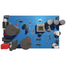
Understanding UCC28740DR Functionality

Check the schematic for any issues that can cause this project not to work. Check all components specs, like voltage rating for capacitors, power rating for resistors, current rating for inductors, etc., to meet requirements: The power supply can be powered from 90-264VAC Input. This design uses valley switching fly-back controller UCC28740 controller. The design achieves peak efficiency 86% and can support 3000uF capacitive load with startup time less than 500mS,
Worked for 3 mins 6 sec
I found several work-blocking risks: UCC28740
VDD/VS and LMR33620 VCC are flagged as not driven, transformer pins T2:S2/S2_1 are floating, there are 55 PCB airwire errors, and many generic passives lack voltage/current/power ratings needed for signoff. Full findings and recommended fixes are in Power Supply Schematic Review.Check the datasheet for transformer T2 in this project and calculate what voltages I will actually get
750343466.pdf
Worked for 1 min 33 sec
T2 is intended to produce ~24 VDC on the main isolated output and ~16.5 V on the auxiliary winding, but the current schematic appears to wire the secondary incorrectly: the datasheet says to tie pins 8+9 together and 12+13 together, while pins 12/13 are floating in the project. That means the actual output voltage is currently undefined / likely not working until T2 is rewired per the datasheet. Full calculation and schematic notes are in Transformer T2 Voltage Check — Würth 750343466.
Fix T2 wiring
Run ERC/DRC
Check D6 orientation
Calculate after D6
Refine this doc
Ask about this doc
UCC28740DR Part Explanation
One-sentence summary
UCC28740DR is a Texas Instruments offline isolated flyback power-supply controller that regulates a flyback converter in constant-voltage/constant-current operation using optocoupled secondary feedback for voltage regulation and primary-side regulation for current limiting.
What this part is doing in this project
In this 40 W AC-DC isolated power supply, U2 (UCC28740DR) is the primary-side flyback controller. It drives the external high-voltage MOSFET, senses primary current, monitors transformer auxiliary winding information, receives isolated feedback through an optocoupler path, and manages startup/protection behavior.
From the schematic:
Table
| U2 pin | Net / connected function | Circuit role |
|---|---|---|
| VDD, pin 1 | Net 9: C15, C14, D1 | Controller bias supply, likely powered initially by HV startup and then by auxiliary winding through D1. |
| VS, pin 2 | Net 10: R16, R14 | Auxiliary-winding sense input for output-voltage reflection, demagnetization timing, line sensing, and protection. |
| FB, pin 3 | Net 14: R10, R4, C23 | Optocoupler feedback input from the secondary-side regulation loop. |
| GND, pin 4 | Net 29 | Primary-side controller reference/return. |
| CS, pin 5 | Net 15: C18, R5 | Current-sense input for primary switch peak-current control. |
| DRV, pin 6 | Net 16: R13 | Gate-drive output to the external MOSFET gate network. |
| HV, pin 8 | Net 19: rectified/bulk bus network | High-voltage startup input tied to the rectified bulk/input bus. |
Purpose and key functions
The UCC28740 is intended for isolated AC/DC flyback supplies where low standby power, good transient response, and controlled output current are important. Its main functions are:
- Flyback PWM/control law for an external primary MOSFET.
- Constant-voltage regulation through optocoupled feedback from the secondary side.
- Constant-current regulation using primary-side sensing information.
- Integrated high-voltage startup through a 700 V startup switch, reducing the need for a lossy startup resistor network.
- Valley switching / quasi-resonant operation in discontinuous conduction mode to reduce switching loss and EMI.
- Frequency modulation and peak-current modulation to maintain efficiency over line and load.
- Low no-load power capability, specified by TI as less than 10 mW in suitable designs.
- Protection features, including output overvoltage, input undervoltage/low-line behavior, overcurrent, overtemperature, CS/VS fault handling, and restart behavior.
How it operates in a circuit
Startup
At startup, the controller uses its HV pin connected to the rectified bulk voltage to charge the VDD capacitor. Once VDD reaches the controller’s UVLO turn-on threshold, the internal startup source turns off and the IC begins switching. After the converter starts, the auxiliary winding normally supplies VDD through a rectifier path.
Switching control
The DRV pin drives the external MOSFET gate. The MOSFET applies pulses to the transformer primary. During each cycle, current ramps in the primary winding and is measured at the CS pin through a current-sense resistor network. The IC uses this signal to terminate switching pulses and control peak primary current.
Output regulation
For constant-voltage regulation, the secondary side senses the output voltage, typically through a TL431-style shunt regulator and optocoupler. The optocoupler signal returns to the primary side at the FB pin. The UCC28740 converts that feedback current into its internal control-law command, adjusting switching frequency and peak-current level to maintain the output voltage.
For constant-current behavior, the IC uses VS pin timing and CS pin current information to estimate and regulate secondary output current without direct secondary-side current measurement.
Auxiliary-winding sensing
The VS pin is connected to a divider from the transformer auxiliary winding. This pin is central to several functions:
- demagnetization timing,
- output-voltage reflection monitoring,
- valley-switch timing,
- line/run-stop sensing,
- output overvoltage detection,
- fault detection if auxiliary feedback is missing or abnormal.
Efficiency and EMI behavior
The controller operates in discontinuous conduction mode and uses valley switching so the MOSFET turns on near a low point in its drain-voltage ringing waveform. This reduces turn-on loss and can reduce conducted/radiated EMI. The controller also uses frequency dithering in parts of its operating range to help with EMI compliance.
Common applications
Typical applications include:
- USB-compliant adapters and chargers,
- consumer electronics power adapters,
- TV and desktop standby supplies,
- appliance / white-goods auxiliary power supplies,
- isolated offline power supplies needing low standby power and CV/CC behavior.
This project uses it in a higher-power industrial-style isolated AC/DC supply, which is consistent with the same flyback-control role, though the surrounding transformer, MOSFET, rectifiers, EMI filter, and output stages set the actual power rating.
Notable characteristics
- Secondary-side optocoupled CV regulation gives better voltage transient behavior than pure primary-side regulation.
- Primary-side CC regulation allows current limiting without a secondary-side current-sense amplifier.
- Integrated 700 V startup improves standby efficiency compared with simple resistive startup.
- SOIC-7 package uses physical pins 1–6 and 8; pin 7 is absent/not used in the package convention.
- External MOSFET architecture lets the designer scale the power stage by choosing the MOSFET, transformer, snubber, sense resistor, and rectifiers.
- Designed for isolated flyback converters, not non-isolated buck/boost converters.
Family / series context
The UCC28740 belongs to TI’s broader UCC287xx flyback-controller family, which covers offline flyback controllers optimized for low standby power, CV/CC regulation, primary-side or secondary-side regulation, and quasi-resonant/valley-switching behavior.
Table
| Device | Relationship / key difference | Typical use case |
|---|---|---|
| UCC28740 / UCC28740D / UCC28740DR | Same controller; D/DR are ordering/package variants. DR is tape-and-reel. | Offline isolated CV/CC flyback supplies using optocoupled voltage feedback and integrated HV startup. |
| UCC28740-Q1 | Automotive-qualified version of the UCC28740 family. | Automotive or high-reliability designs requiring Q1 qualification. |
| UCC28730 | Similar broader UCC287xx flyback-controller family member, but focused on zero/very-low standby primary-side regulation with wake-up monitoring rather than the same optocoupled secondary-side regulation architecture. | Designs prioritizing extremely low standby power and PSR-style feedback. |
| UCC28742 | Similar SSR flyback-controller concept, but in a smaller SOT-23-6 style implementation; it does not include the same HV startup pin/internal startup FET and does not provide the same CC operating mode as UCC28740. | Smaller, simpler SSR flyback designs where integrated HV startup and full CV/CC behavior are not required. |
Compared with other controller approaches
- Versus pure PSR flyback controllers: UCC28740 adds optocoupled feedback for constant-voltage regulation, improving transient response and accuracy at the cost of secondary feedback components.
- Versus fixed-frequency PWM flyback controllers: UCC28740’s valley switching, frequency modulation, and light-load behavior are optimized for efficiency and low standby power rather than a fixed switching frequency.
- Versus integrated switcher ICs: UCC28740 uses an external MOSFET, giving more design flexibility and power scalability, but requiring careful transformer, MOSFET, snubber, layout, and compensation design.
Practical design implications
When using this part, the most important surrounding design elements are:
- Transformer auxiliary winding and VS divider — must provide correct reflected-voltage and timing information.
- VDD capacitor and auxiliary bias path — must support startup and normal operation without UVLO cycling.
- Current-sense resistor network — sets peak-current behavior and affects output current limiting.
- Optocoupler/TL431 feedback loop — determines output-voltage regulation and transient behavior.
- MOSFET gate network and snubber/clamp — strongly affects EMI, switching loss, and reliability.
- Primary/secondary isolation layout — critical because this is an offline isolated AC/DC supply controller.
Source basis
This explanation is based on the project schematic/BOM data for U2 = UCC28740DR and the official Texas Instruments UCC28740 datasheet/product information, including the datasheet description of CV/CC flyback control, optocoupled feedback, integrated high-voltage startup, DCM valley switching, protection behavior, package/ordering information, and related-device context.
One-sentence summary
What this part is doing in this project
Purpose and key functions
How it operates in a circuit
Startup
Switching control
Output regulation
Auxiliary-winding sensing
Efficiency and EMI behavior
Common applications
Notable characteristics
Family / series context
Closely related devices
Compared with other controller approaches
Practical design implications
Source basis