Project Overview and Optimization
Thought for 3 mins 39 sec
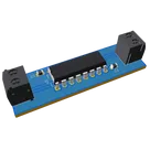
Here’s a concise technical walkthrough of your “L293D Motor driver Module” project based on the current schematic/netlist.
What it is and purpose
- A dual DC motor driver module built around U1, intended to independently drive two brushed DC motors with separate logic and motor supplies. Typical uses: small robots, rovers, pan/tilt mechanisms, and general two-motor control.
Core components and roles
- Driver IC: U1 (L293D) – Dual H-bridge driver. Two channels (1/2) form one H-bridge; channels (3/4) form the second.
- Motor outputs:
- Control inputs:
- Power:
- Reference motor symbol: M3 (generic DC motor) appears illustrative.
How it works (signal interaction)
- Per the L293D datasheet (TI/ST):
- VCC1 is the logic/inputs supply; VCC2 is the motor/output supply. Drivers are enabled in pairs (EN1,2 for channels 1/2; EN3,4 for 3/4).
- Truth table (per channel): Enable=H, A=H -> Y=H; Enable=H, A=L -> Y=L; Enable=L -> Y=Z (high-Z). Using two channels as an H-bridge, one side driven high and the other low sets motor direction. Swapping the inputs reverses direction.
Current design state and connectivity observations
- Power nets:
- Inputs/enable:
- Motor outputs:
- Motor B is correctly split: M2 P1 -> U1:3Y and P2 -> U1:4Y (separate nets).
- Motor A appears shorted: Net "Net (M1 - P2)" includes M1 P1 and P2 plus U1:1Y and U1:2Y on the same net. That ties both H-bridge outputs together and both motor terminals together, which prevents differential drive and risks the driver. This needs to be split into two distinct nets: one for 1Y->M1:A and another for 2Y->M1:B.
Design choices, trade-offs, and optimizations
- Two-supply architecture: Separate logic (VCC1) and motor (VCC2) rails is a good practice to isolate noisy load currents from logic.
- Internal clamp diodes: L293D includes output clamp (flyback) diodes for inductive loads. This simplifies the BOM, though diode current/thermal limits still apply.
- Decoupling:
- Place a small-value decoupler at each supply pin and a nearby bulk cap. Knowledge-base guidance: position the smallest value directly at the IC power pin and the larger capacitor nearby (e.g., 0.1uF at the pin and 10uF adjacent). Ensure capacitors operate at no more than 60% of their maximum rated voltage.
- Technology trade-off: L293D uses a bipolar transistor output stage. Versus modern MOSFET H-bridges, this typically incurs higher conduction loss and more heat for the same load. It’s robust and simple, but less efficient.
Potential challenges and performance considerations
- Incorrect net for Motor A: The shorted outputs/net must be corrected before layout or testing.
- Missing external connectivity: Logic/motor supply terminals and control/enable terminals need to be tied to the same nets as the IC pins and portals.
- Supply integrity:
- Motor current creates large transients. Without adequate bulk capacitance and tight decoupling at VCC2, you can see resets/noise on logic. Keep loop areas small; return high di/dt currents directly to the GND node near U1.
- Thermal headroom: H-bridge loss manifests as heat in U1; ensure operating current and ambient allow safe junction temperature, and provide copper for heat spreading.
- Inductive kickback: While the L293D includes internal diodes, validate they meet worst-case energy for your motors; consider external suppression (TVS on VCC2, RC snubbers, or ferrite) if needed.
- Grounding: Use a solid ground reference and avoid sharing high-current motor returns with sensitive logic return paths to reduce ground bounce.
Real-world applications
- Differential drive robots (two wheels), conveyor belts, small positioners, and any system needing two DC motors with direction control and optional speed control (via PWM on INx or ENx).
Areas for improvement and future enhancements
- Electrical fixes:
- Power robustness:
- Add clearly specified bulk capacitance on VCC2 near U1 and the motor terminals; follow the placement guidance above and capacitor derating rule (operate at no more than 60% of rated voltage).
- Consider a TVS diode on the VCC2 input and reverse-polarity protection on the motor supply terminal.
- Control interface:
- Layout guidance (next stage):
- Keep C1 (logic) and C2 (motor) as close to U1 pins as possible (0.1uF at the pin, bulk adjacent); route high-current paths short and wide; maintain a continuous ground reference; separate motor return from logic return where possible before they meet at a solid plane.
- Scalability and alternatives:
Would you like me to fix the Motor A net, connect the terminals to the correct nets, and add finalized decoupling in this project? If yes, tell me your logic voltage for VCC1 and the motor supply range for VCC2, and I can proceed.
Check motor A nets
Verify power connectivity
Pick better driver option
Decoupling recommendation


carlosrocka
copilot