Part Datasheet Audit
Thought for 2 mins 19 sec
I checked it using a datasheet-first part audit workflow for part projects .
- Datasheet URL: already set to the official XFCN PDF, so no update is needed.
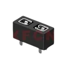
- Key specs from datasheet: automotive blade fuse holder, 500 V, 15 A to 30 A, -40 C to 125 C, 4 PCB terminals, through-hole, 4 x 1.6 mm minimum holes.
- Symbol: matches the datasheet on 4 terminals. Generic numbering is acceptable because the datasheet does not provide individual terminal names/numbers.
- Footprint: has 4 pads, which is directionally correct, but I could not fully verify pad geometry/hole diameter from the available layout data alone.
- Pin descriptions: no individual terminal descriptions are defined in the datasheet, so there is nothing detailed to cross-check there.
Flags
- Package or Case Code =
TOlooks questionable. The datasheet supports through-hole PCB fuse holder / 4 PCB terminals, not a TO package. - Pin Type = Unspecified on all four terminals is not contradicted by the datasheet, but it is also not enriched.
- Full mechanical verification is still incomplete until pad drill/pad-size values are exposed for comparison.
I’ve prepared a plan to formalize this audit/update flow. Click Start on the plan bar if you want that executed.
Fix package metadata
Check remaining geometry
Review all other parts
To get started, talk to Flux or create a New Document.