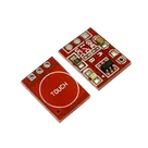
TTP223 Pad Connections
Thought for 3 sec
I’ll check the module schematic/connectivity so I can explain exactly how the three pads map to GND, IO, and VCC.
Thought for 10 sec
The schematic currently shows three terminal pads labeled VCC, I/O, and GND, but no nets/wires have been defined yet. So electrically, Flux does not currently show them connected to anything else.
Conceptually on a TTP223 touch module:
- VCC pad → power input, typically 2.0–5.5 V depending on the module/IC version
- GND pad → ground/common reference
- I/O pad → digital touch output signal to your Arduino/MCU input pin
So you would wire it like:
Text
TTP223 VCC → Arduino 5V or 3.3V TTP223 GND → Arduino GND TTP223 I/O → Arduino digital input pin
The touch pad electrode itself is not one of those three external pads; it connects internally to the TTP223 sensor input. The three exposed pads are just the power and output interface.
Show internal wiring
Check PCB pads
Add Arduino header
Run design review
Explain output behavior