Treat Flux like your intern. Tell it what you'd like to build and it'll get to work. You can also ask it questions, brainstorm ideas, and teach it your preferences. Learn More
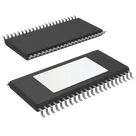
Sure, I can help with that. However, to move forward we would first need more information on the rest of your system. It seems you are working with the TPA3255DDV, a Class D stereo amplifier IC by Texas Instruments. This IC can support four different audio inputs and four different audio outputs, suggesting it can be driven in different configurations: two-channel (stereo), three-channel, or four-channel (quadraphonic).
To keep things simple, let's start by designing a basic circuit for a stereo amplifier.
Here are the major components of a typical stereo amplifier using TPA3255DDV:
The TPA3255DDV Class-D amplifier itself
Input sources (audio signals)
Power Supply unit
Output endpoints (speakers)
Here's a high-level connection list for the above-listed components:
Audio Inputs:
Connect INPUT_A and INPUT_B to your audio source.
Audio Outputs:
Connect each output (OUT_A_1, OUT_A_2, OUT_B, and OUT_C) to its corresponding speaker terminal.
Power Supply:
Power supply voltages should be connected to PVDD_AB_1, PVDD_AB_2, PVDD_AB_3, PVDD_CD_1, PVDD_CD_2, PVDD_CD_3, GVDD_AB, and GVDD_CD.
Ground Connections:
Ground connections should be made to GND_1, GND_2, GND_3, GND_4, GND_5, GND_6, GND_7, and GND_8.
Boost Supply:
For the boost supply BST_A, BST_B, BST_C, and BST_D are used.
Digital functions:
M1 and M2 control the operating mode (stereo, PBTL or quad).
An open-drain FAULT pin indicates undervoltage and overtemperature conditions.
The power supply tracking is achieved by DVDD, AVDD and VDD pins.
Other Inputs:
FREQ_ADJ can be used to adjust the switching frequency.
OC_ADJ can be used to change the overcurrent threshold.
Other pins like ~RESET, ~CLIP_OTW, and VBG are there for reset, clip and Over Temperature Warning (OTW), and to supply the voltage reference respectively.
Please note, this is a general direction of how connections could be made. Let's get more information on your system requirements to proceed with a more detailed design.
Note: For all these connections, based on your supply voltage and other system requirements, some components might need specific capacitor, resistor or inductor values. I recommend checking the datasheet or reference guide for this IC to see the manufacturer's recommended component values and configurations, as these will vary based on the specifics of your application.
2y
Someone is typing...
3
OUT_C
C_START
GVDD_AB
OUT_B
GND_4
BST_A
VDD
PVDD_AB_1
GVDD_CD
INPUT_A
OC_ADJ
GND_6
OUT_D_2
OUT_D_1
OSC_IOP
OSC_IOM
GND_2
M2
VBG
GND_5
BST_B
DVDD
BST_D
BST_C
PVDD_CD_3
~CLIP_OTW
INPUT_B
GND_3
PVDD_CD_2
~RESET
PVDD_CD_1
M1
INPUT_D
GND_1
PVDD_AB_3
OUT_A_2
GND_8
~FAULT
AVDD
PVDD_AB_2
OUT_A_1
INPUT_C
GND_7
FREQ_ADJ
No files yet
Reviews
Documents
Documents are markdown text files which describe project goals, capture details, or even simulation outputs.
daron_silver164867
copilot
INPUT_AandINPUT_Bto your audio source.OUT_A_1,OUT_A_2,OUT_B, andOUT_C) to its corresponding speaker terminal.PVDD_AB_1,PVDD_AB_2,PVDD_AB_3,PVDD_CD_1,PVDD_CD_2,PVDD_CD_3,GVDD_AB, andGVDD_CD.GND_1,GND_2,GND_3,GND_4,GND_5,GND_6,GND_7, andGND_8.BST_A,BST_B,BST_C, andBST_Dare used.M1andM2control the operating mode (stereo, PBTL or quad).FAULTpin indicates undervoltage and overtemperature conditions.DVDD,AVDDandVDDpins.FREQ_ADJcan be used to adjust the switching frequency.OC_ADJcan be used to change the overcurrent threshold.~RESET,~CLIP_OTW, andVBGare there for reset, clip and Over Temperature Warning (OTW), and to supply the voltage reference respectively.