Part Datasheet Review and Validation

Fix the metadata, populate pin descriptions and types, then rerun a symbol/footprint review.
Thought for 7 sec
I’ll update the part metadata and terminal pin properties from the Infineon datasheet, then re-inspect the schematic symbol and footprint for mismatches.
Thought for 39 sec
Metadata is corrected; I’m now applying datasheet-derived pin descriptions and electrical types to all 37 terminals.
Worked for 1 min 51 sec
Fixed the metadata and populated all 37 terminal Pin Description and Pin Type properties from the Infineon datasheet. I reran the review: symbol pin mapping and footprint pad count now match the datasheet, with no remaining pin-name/number/description mismatches.
Open items:
- Exact footprint copper/mask/stencil geometry could not be numerically verified from the exposed layout data, but pad count/designators and visible package form are consistent with PG-DSO-36-72.
Updated review file: TLE92466EDXUMA1 Part Datasheet Cross-Check.
Fix footprint and review
Verify footprint geometry
Run ERC and DRC
Check BOM readiness
Add thermal notes
Refine this doc
Ask about this doc
TLE92466EDXUMA1 Part Datasheet Cross-Check
Status after metadata and pin-property fixes
Review rerun after updating project metadata, terminal pin descriptions, and terminal pin types.
Updated project metadata verified
- Manufacturer Part Number: TLE92466EDXUMA1
- Manufacturer: Infineon Technologies
- Part Type: Integrated Circuit
- Domain: Automotive
- Compliance: AEC-Q100
- Operating Voltage: 40 V
- Operating Temperature: 175 °C
- Designator Prefix: IC
- Current Datasheet URL: https://www.infineon.com/assets/row/public/documents/10/49/infineon-tle92466ed-datasheet-en.pdf?fileId=5546d4627883d7e00178c67d6af95b96
- Description now identifies the device as a six-channel low-side solenoid driver IC and clarifies that 2.7 A applies to parallel-channel mode.
Datasheet key specs
- Device: TLE92466ED, six-channel low-side solenoid driver IC.
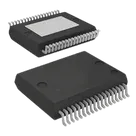
- Package: PG-DSO-36 Dual-Gauge (300 mil), Infineon variant PG-DSO-36-72.
- Terminals: 36 leads plus exposed cooling tap/paddle, represented as pin/pad 37.
- Function: Integrated MOSFET low-side drivers with current sensing for six linear solenoids.
- Channels: 6 independent low-side channels.
- Current control: 0 mA to 1.5 A programmable setpoint, 15-bit resolution.
- Dither/load capability: Up to 1.8 A including dither in single-channel operation.
- Parallel-channel measurement/current capability: Up to 2.7 A.
- Typical RDS(on): 115 mΩ; max 200 mΩ at TJ = 150°C and ILOADx = 2 A.
- Integrated shunt: typ 140 mΩ.
- SPI: 32-bit SPI with 8-bit CRC and watchdog.
- Logic levels: SPI/control inputs support 3.3 V or 5 V logic where applicable.
- Functional ranges: VDD 4.5–5.5 V nominal, VBAT 6–18 V nominal, VIO 3.0–5.5 V nominal.
- Extended ranges: VDD 3.5–19 V, VBAT 4–38 V, VIO up to 19 V per datasheet conditions.
- Temperature: -40°C to 175°C junction range noted in features; AEC-Q100 Grade 0.
- Safety: ISO 26262 Safety Element out of Context up to ASIL C.
Symbol pin review after fixes
The schematic symbol contains 37 terminal components, matching the datasheet's 36 package leads plus exposed cooling tap. Pin number/name mapping matches the datasheet, and every terminal now has a datasheet-derived Pin Description and a valid Flux Pin Type.
Table
| Pin | Datasheet symbol | Project terminal | Pin Type | Status |
|---|---|---|---|---|
| 1 | LOAD0 | LOAD0 | Output | OK |
| 2 | FWD0 | FWD0 | Output | OK |
| 3 | GNDP0 | GNDP0 | Ground | OK |
| 4 | GND | GND_1 | Ground | OK |
| 5 | CSN | CSN | Input | OK |
| 6 | SCK | SCK | Input | OK |
| 7 | SI | SI | Input | OK |
| 8 | VIO | VIO | Power In | OK |
| 9 | SO | SO | Output | OK |
| 10 | GND | GND_2 | Ground | OK |
| 11 | FAULTN | FAULTN | Open Collector | OK; used to represent open-drain status output |
| 12 | GND | GND_3 | Ground | OK |
| 13 | LOAD5 | LOAD5 | Output | OK |
| 14 | FWD5 | FWD5 | Output | OK |
| 15 | GNDP5 | GNDP5 | Ground | OK |
| 16 | GNDP1 | GNDP1 | Ground | OK |
| 17 | FWD1 | FWD1 | Output | OK |
| 18 | LOAD1 | LOAD1 | Output | OK |
| 19 | LOAD2 | LOAD2 | Output | OK |
| 20 | FWD2 | FWD2 | Output | OK |
| 21 | GNDP2 | GNDP2 | Ground | OK |
| 22 | VBAT | VBAT | Power In | OK |
| 23 | GND | GND_4 | Ground | OK |
| 24 | CLK | CLK | Input | OK |
| 25 | DRV0 | DRV0 | Input | OK |
| 26 | RESN | RESN | Input | OK |
| 27 | EN | EN | Input | OK |
| 28 | DRV1 | DRV1 | Input | OK |
| 29 | VDD | VDD | Power In | OK |
| 30 | GND | GND_5 | Ground | OK |
| 31 | LOAD4 | LOAD4 | Output | OK |
| 32 | FWD4 | FWD4 | Output | OK |
| 33 | GNDP4 | GNDP4 | Ground | OK |
| 34 | GNDP3 | GNDP3 | Ground | OK |
| 35 | FWD3 | FWD3 | Output | OK |
| 36 | LOAD3 | LOAD3 | Output | OK |
| 37 | Cooling Tap | GND_6 | Ground | OK; description identifies Cooling Tap / exposed pad |
Footprint review after fixes
- Layout contains 37 pads matching the datasheet's 36 leads plus exposed cooling tap.
- Pad designators match all symbol terminals.
- Package family/variant remains consistent with PG-DSO-36-72.
- Visible outline/lead pitch pattern remains consistent with PG-DSO-36 exposed-pad footprint.
- Detailed pad geometry values were not fully exposed in the layout inspection output, so exact copper/solder-mask/stencil dimensions were not numerically revalidated.
Remaining notes
No symbol pin-number, pin-name, pin-description, or footprint pad-count mismatches were found after the fixes. The only remaining limitation is that exact footprint geometry could not be numerically verified from the currently exposed layout data.
Status after metadata and pin-property fixes
Updated project metadata verified
Datasheet key specs
Symbol pin review after fixes
Footprint review after fixes
Remaining notes