Treat Flux like your intern. Tell it what you'd like to build and it'll get to work. You can also ask it questions, brainstorm ideas, and teach it your preferences. Learn More
This schematic appears to be a simple voltage-controlled switch circuit, designed to automatically disconnect a load when a certain voltage level is reached, commonly used with solar panels or DC power sources to prevent overcharging.
Let's break down key components and how they might relate to the TIP41BG in your project:
Entrada (Input) 14 to 20V: This is the DC power source, such as a solar panel.
Zener diode (12V, 1/4W): This component is used to set the voltage threshold for switching. It provides a reference voltage.
Potentiometer (trimpot 5k): This is used to adjust the voltage level where the circuit will turn off the power to the load.
Resistor (470Ω) and Resistor (1kΩ): These resistors are used for current limiting and to form a voltage divider with the zener diode and trimpot.
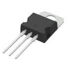
TIP41C: This is a NPN power transistor similar to the TIP41BG mentioned in your project. It acts as a switch that controls the relay.
Relay (12V, 5 pins): This relay is used to connect/disconnect the battery or load based on the controlling signal from the transistor.
LED: The LED provides a visual indication that the circuit is active.
Bateria (Battery 12V): This represents the load or the battery being charged.
To incorporate the TIP41BG into this design, you can place it in the same position as the TIP41C in the schematic.
Would you like help with any specific part of designing or modifying this circuit in Flux? Feel free to ask!
1y
Someone is typing...
3
E
C
B
No files yet
Reviews
Documents
Documents are markdown text files which describe project goals, capture details, or even simulation outputs.
makot
Image
copilot