Stereo Line Driver Design
Thought
Work completed:
- Project description updated and system architecture defined with Mermaid diagram.
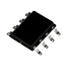
- Two THAT1646S08-U devices and optional SMF05CT2G ESD diodes added.
- Power subsystem set to single-supply (5–18 V); DC barrel jack and decoupling capacitors (100 nF and 10 µF per rail) placed.
- Balanced I/O connectors (two NC3FAH1 female for inputs, two TRAPC3MSX male for outputs) added.
- Input networks (R1/R2, C10/C11) and output/sense networks (R3/R4, C12–C15) added and net-connected per datasheet.
- VCC/VEE rails, decoupling capacitors, AGND/shields, and a ground-lift jumper all wired.
- ERC errors for decoupling, resistor power ratings, pull-ups/pull-downs, and capacitor voltage ratings addressed.
Remaining tasks:
- Fetch and record absolute maximum and recommended operating supply voltages from the THAT1646S08-U datasheet (project properties: “Absolute Max Supply Voltage (VCC)”, “Absolute Max Supply Voltage (VEE)”, “Recommended Min Supply Voltage”, “Recommended Max Supply Voltage”).
- Verify that VCC/VEE nets fall within the recommended operating range and set “Supply Voltage Range Verified”.
- Prepare PCB layout: assign footprints, configure stackup and ground/power planes, place components, run DRC, and export manufacturing files.
Success criteria status:
- ✅ Schematic includes two THAT1646S08-U devices with decoupling, support networks, and protection.
- ✅ All connectors correctly implemented.
- ⚠️ PCB layout and DRC not yet done.
- ⚠️ Manufacturing files not yet generated.
Next step:
Use the @datasheet tool to query the THAT1646S08-U’s absolute maximum and recommended operating supply voltages, add those values as project properties, and verify net voltages before moving on to PCB layout.
Flux stopped